
Apparatus at a spinning preparation machine, especially a flat card, roller card or the like, for ascertaining carding process variables

a technology of preparation machine and carding element, which is applied in the field of flat card, roller card, etc., can solve the problems of increasing the sagging of the carding element, the high weight of the carding force sensor, and the high mass inertia of such a system

Inactive Publication Date: 2007-11-22
TRUETZSCHLER GMBH & CO KG
View PDF3 Cites 34 Cited by
  • Summary
  • Abstract
  • Description
  • Claims
  • Application Information

AI Technical Summary

Benefits of technology

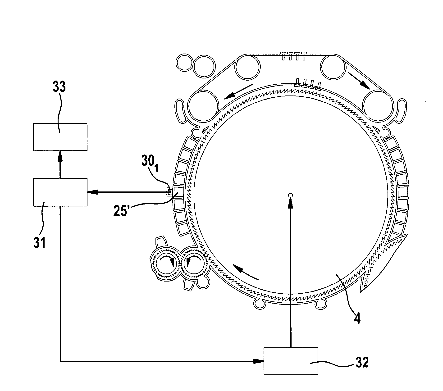
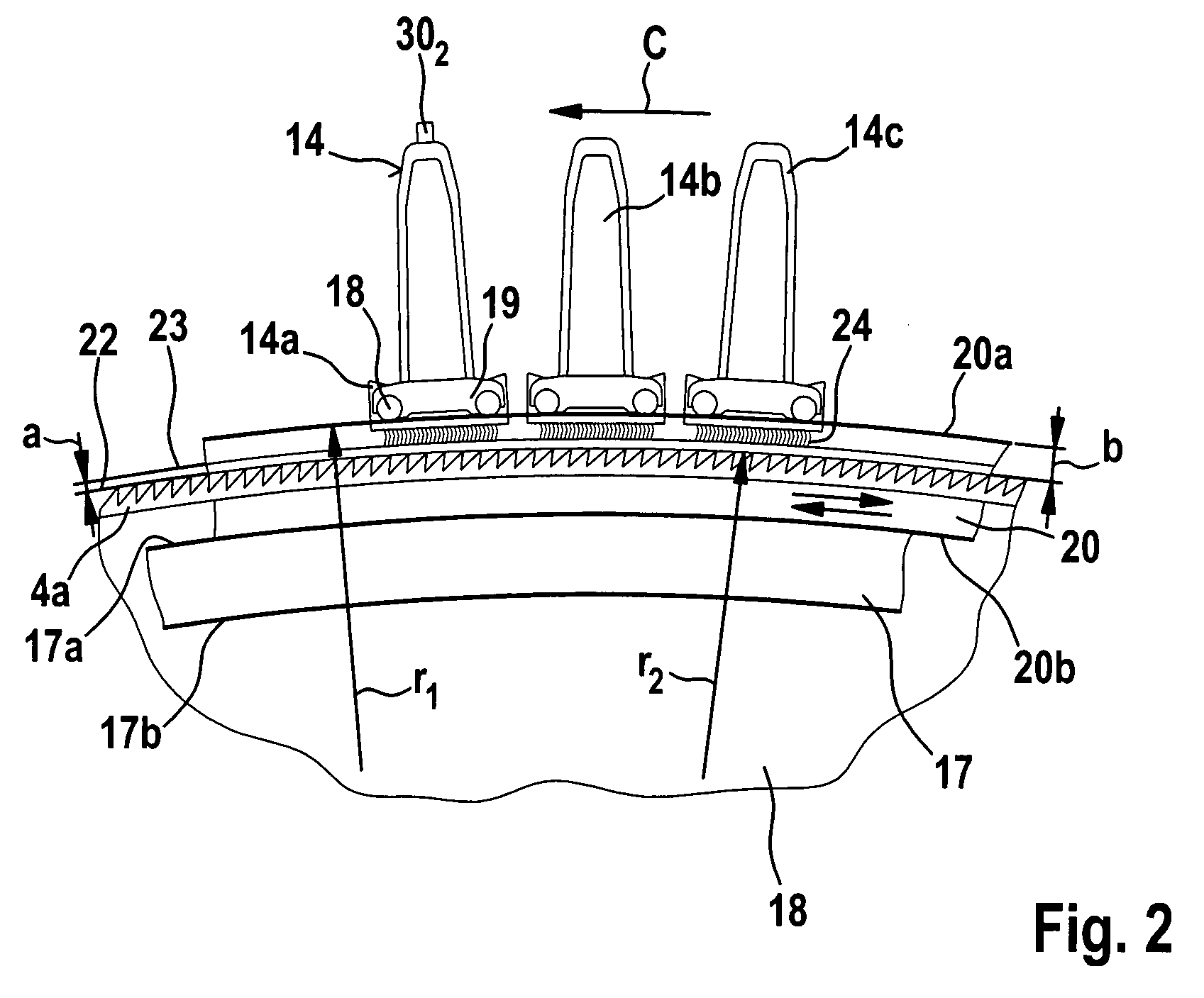
[0006]As a result of the fact that the piezoceramic sensor is a structure-borne sound sensor of high sensitivity, which is associated with a component and in contact therewith, it is possible to ascertain the carding intensity by means that are simple in terms of construction. The structure-borne sound sensor is merely coupled up to a component in which structure-borne sound vibrations occur, as a result of which those structure-borne sound vibrations also pass into and flow through the structure-borne sound sensor, and the vibrations can be detected by means of a measurement arrangement. If the structure-borne sound sensor and the fixed carding element are so constructed that, for example, their connection is, advantageously, magnetic in nature, the structure-borne sound sensor can, in the course of continuing production, be moved from carding element to carding element, being placed thereon, and the carding intensity can be measured. It is accordingly possible, within the shortest time, to investigate all the carding locations of a flat card, including the card top, with regard to the carding intensity thereof, in the course of continuing production. As a result of the fact that the structure-borne sound sensor, which is, for example, a small cuboid, is fixed in, for example, an existing fixed carding element or revolving card top, functions of the fixed carding element or revolving card top are in no way curtailed by a change in geometry etc.
[0007]In the course of carding, the fibres produce a transverse vibration in the clothing, which propagates through the entire carding component. If the piezo sensor is attached to a carding component through which vibrations pass, the vibration also runs through this mounted sensor. Consequently, the vibration also causes deformation of that component, that is to say the vibration can be described by means of the piezo sensor. Even in the case of a constant force at the clothing, a change in the piezo signal occurs. Electrical filtering of the signal is necessary because the vibrations from other machine regions influence the structure-borne sound measurement. Low-frequency vibrations of all moving components are filtered out. The apparatus is simple in terms of construction, as the piezo sensor merely has to be placed on the component.

Problems solved by technology

It is disadvantageous that the carding forces, which are caused by the fibres between the tips, are minimal and the carding force sensors have a high weight owing to their freely movable carding elements.
A further disadvantage lies in the fact that the mass inertia of such a system is very high.
If the weight of such a sensor is reduced, the rigidity of the system is reduced and sagging of the carding element is increased, whilst the measurement result is falsified because the spacing between the sensor and the roller changes.
Therefore it is not possible, in operation, to move a force sensor from one component to another component without changing settings, that is to say without undoing and re-fixing components, and interrupting lines of force.

Method used


Image

  • Apparatus at a spinning preparation machine, especially a flat card, roller card or the like, for ascertaining carding process variables
  • Apparatus at a spinning preparation machine, especially a flat card, roller card or the like, for ascertaining carding process variables
  • Apparatus at a spinning preparation machine, especially a flat card, roller card or the like, for ascertaining carding process variables

Examples


Embodiment Construction

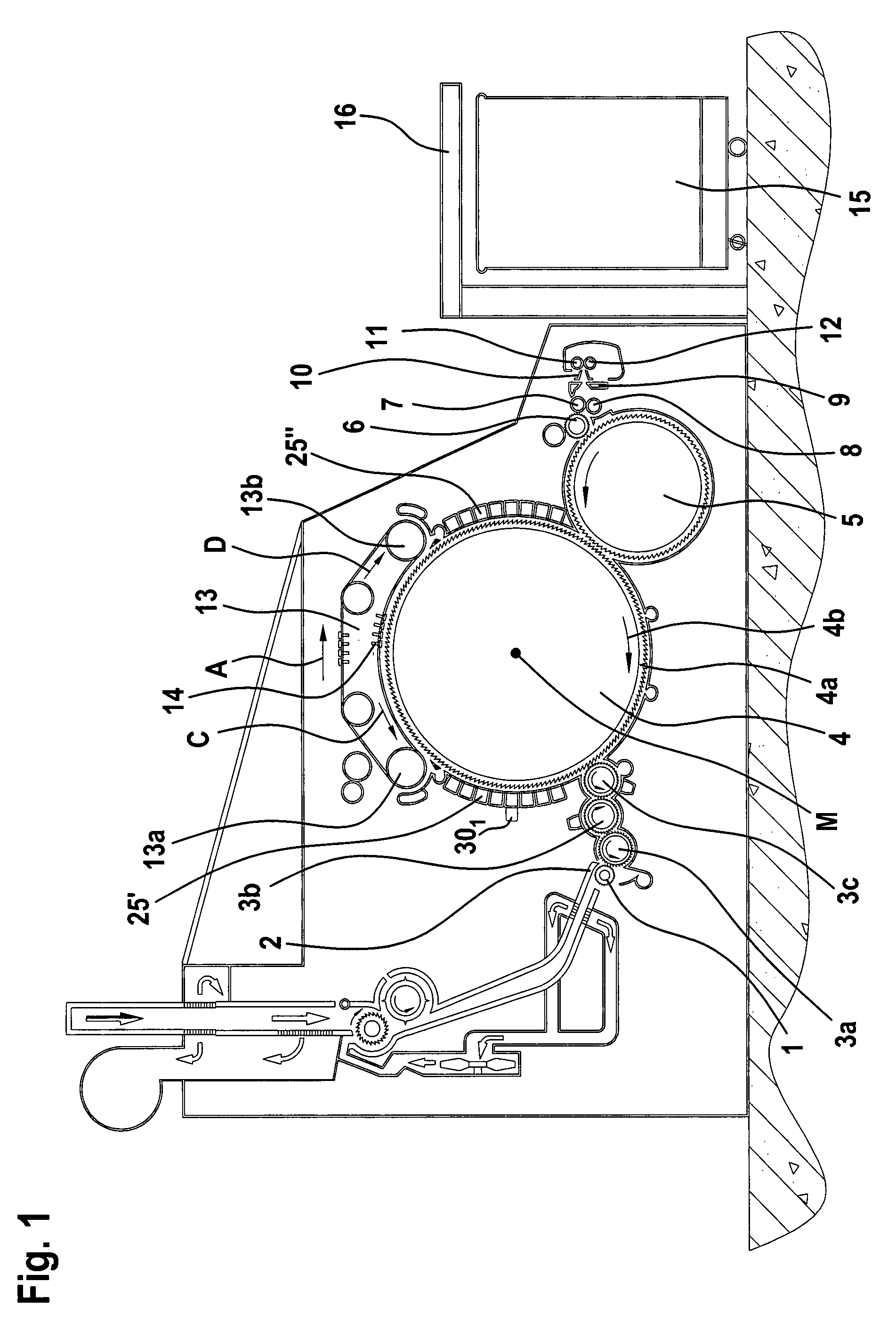
[0027]With reference to FIG. 1, a flat card, for example a TC 03 flat card made by Trützschler GmbH & Co. KG of Mönchengladbach, Germany, has a feed roller 1, feed table 2, lickers-in 3a, 3b, 3c, cylinder 4, doffer 5, stripper roller 6, nip rollers 7, 8, web-guiding element 9, web funnel 10, delivery rollers 11, 12, revolving card top 13 having card top guide rollers 13a, 13b and flats 14, can 15 and can coiler 16. The directions of rotation of the rollers are indicated by curved arrows. Reference letter M denotes the centre (axis) of the cylinder 4 and reference letter A denotes the working direction. Reference 4a denotes the clothing and reference 4b denotes the direction of rotation of the high-speed cylinder 4. Reference letter C denotes the direction in which the revolving card top 13 revolves at the carding location and reference letter D denotes the return transport direction of the flats 14. In the pre-carding region—between the licker-in 3c and the back card top guide rolle...


PUM

PropertyMeasurementUnit
frequenciesaaaaaaaaaa
frequency analysisaaaaaaaaaa

Abstract

In an apparatus at a spinning preparation machine, wherein a clothed roller is located opposite at least one clothed component, there is associated with the component, in contact therewith, a piezoelectric sensor which is connected to an electrical evaluation device in communication with a display device and / or switching device. In order, by simple means to make it possible to ascertain the carding intensity, the piezoelectric sensor is a structure-borne sound sensor and the electrical evaluation device is capable of determining the carding intensity from the structure-borne sound.

Description

CROSS REFERENCE TO RELATED APPLICATION[0001]The present application claims priority from German Patent Application No. 10 2006 024 132.0 dated May 22, 2006, and German Patent of Application No. 10 2007 005 601.1 dated Jan. 31, 2007, the entire disclosure of which are incorporated herein by reference.BACKGROUND TO THE INVENTION[0002]The invention relates to an apparatus at a spinning preparation machine, especially a flat card, roller card or the like, for ascertaining carding process variables, wherein a clothed, rapidly rotating roller is located opposite at least one clothed component.[0003]It is known to associate with the clothed component, in contact therewith, a piezoelectric sensor which is connected to an electrical evaluation device in communication with a display device and / or switching device. More particularly, from EP 1 215 312 A1 it is known, in the case of a revolving card top and a stationary carding segment, to measure the carding forces (shear forces) at both cardi...

Claims


Application Information

Patent Timeline
Patent Type & Authority Applications(United States)
IPC IPC(8): D01G15/00
CPCD01G15/28D01G15/02D01G15/12
Inventor FARBER, CHRISTOPHBREUER, ACHIM
Owner TRUETZSCHLER GMBH & CO KG
Learn More