In-Line Cable Tie with Fixed and Hinged Locking Mechanisms

a technology of fixed and hinged locking mechanisms and cable tie clips, which is applied in the direction of hose connections, machines/engines, transportation and packaging, etc., can solve the problems of high insertion force, high design tensile strength, and high cost of thread insertion force, and achieve substantial flexibility and increase the head length

Active Publication Date: 2007-11-22
PANDUIT
View PDF17 Cites 34 Cited by
  • Summary
  • Abstract
  • Description
  • Claims
  • Application Information

AI Technical Summary

Benefits of technology

[0007] An aspect of the invention is to provide an improved cable tie, preferably an in-line style cable tie, that can achieve a high loop tensile strength and a low thread insertion force. In particular, the invention can achieve up to about 60% higher loop tensile strength than a conventional hinged locking wedge cable tie while achieving up to about a 25-30% decrease in thread insertion force compared to a conventional fixed locking wedge cable tie.
[0011] In accordance with yet another aspect of the invention, a cable tie with hybrid locking mechanism has an increased head length to isolate tensioning and cutoff of the strap from the locking wedges. This results in a cable tie design that is more tolerant of abusive installation practices.
[0012] In accordance with additional aspects of the invention, the cable tie has substantial flexibility due to the strap teeth being provided on both sides of the cable tie body.

Problems solved by technology

Fixed wedge designs can achieve high loop tensile strength compared to flexible hinge wedge designs, but at the expense of a high thread insertion force.
This results in a high insertion force problem.
However, because of the flexible hinge, this type of locking mechanism typically has lower loop tensile strength compared to a fixed locking wedge.
Currently, there are no in-line threading cable ties that achieve the required tensile strength in the electrical contractor market without an excessive thread force.

Method used


Image

  • In-Line Cable Tie with Fixed and Hinged Locking Mechanisms
  • In-Line Cable Tie with Fixed and Hinged Locking Mechanisms
  • In-Line Cable Tie with Fixed and Hinged Locking Mechanisms

Examples


Embodiment Construction

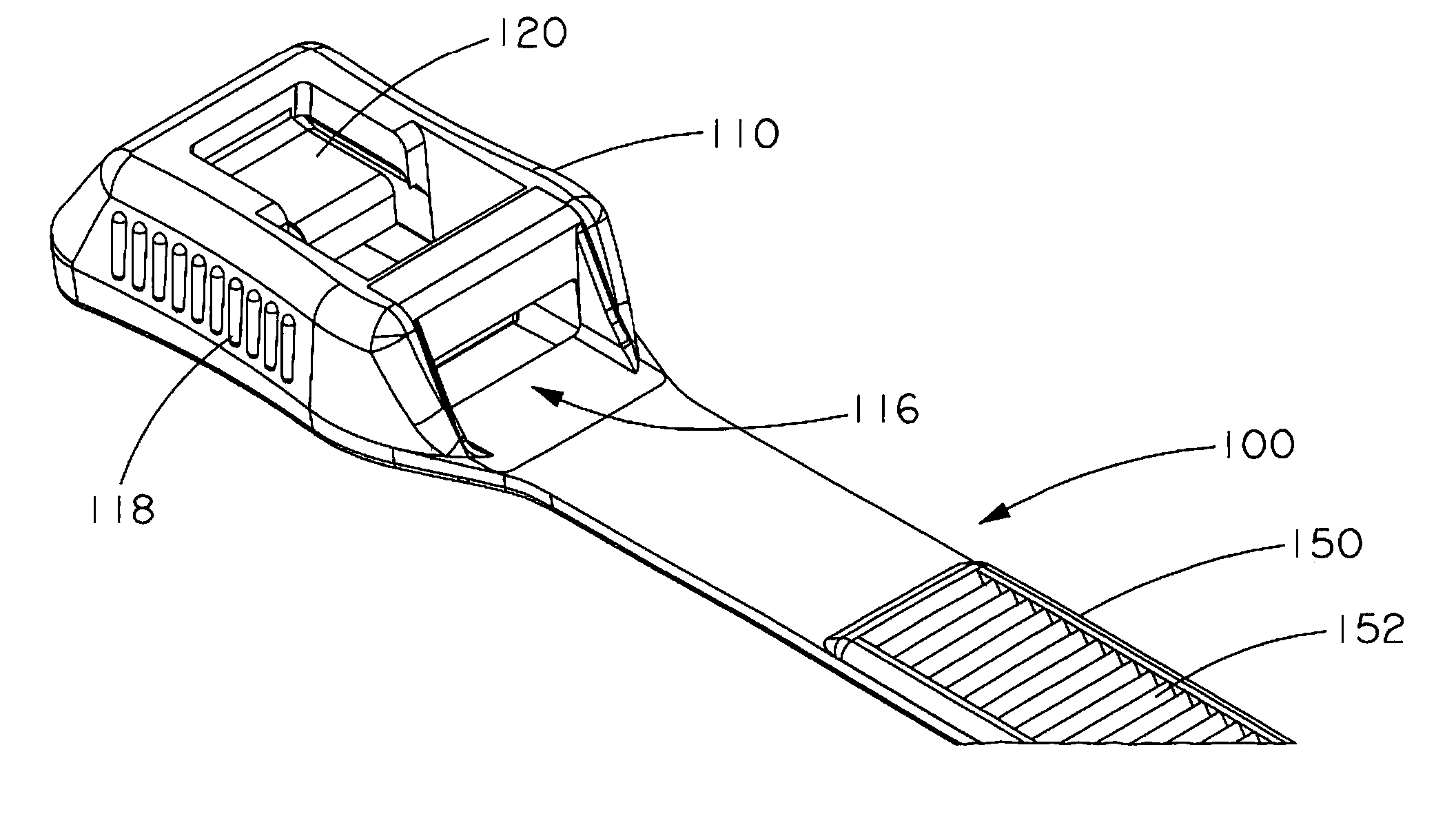
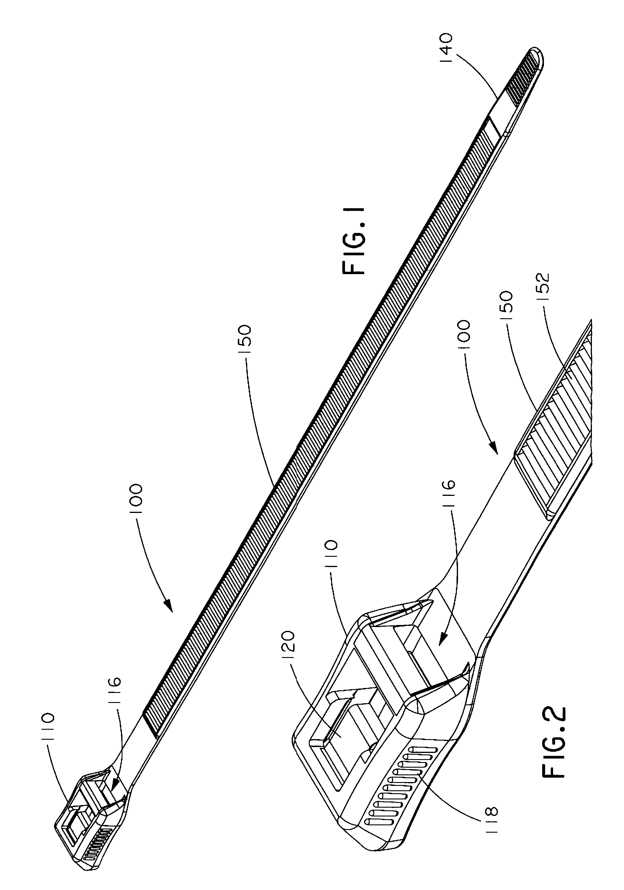
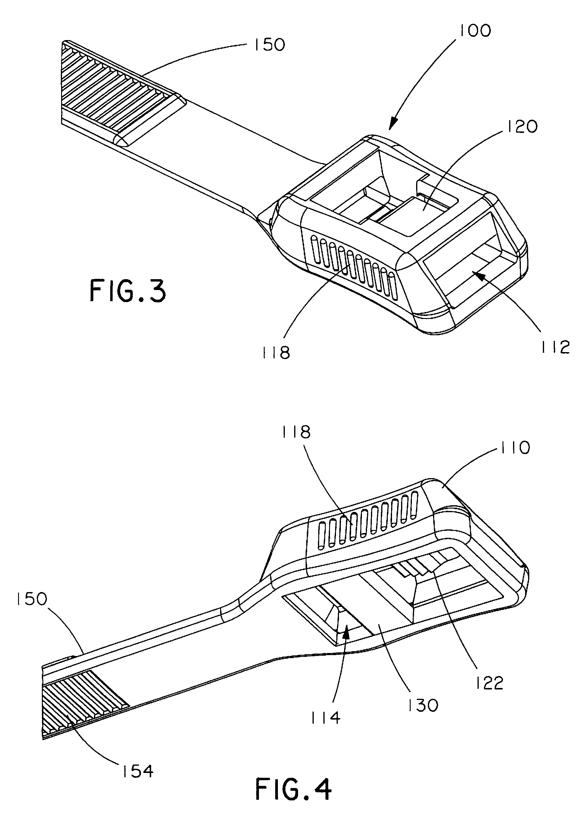
[0028]FIGS. 1-10 show various views of an exemplary cable tie 100 according to the invention. Cable tie 100 includes a cable tie head 110 on one end, a cable strap tail 140 on an opposite end, and an elongated planar strap 150 therebetween. Strap 150 has a thickness T1 (FIG. 8) and two major surfaces. A first major surface forms a top side of the strap and has a plurality of first teeth 152 extending along a substantial portion of the surface (FIG. 5). A second major surface forms a bottom side of the strap and has a plurality of second teeth 154 extending along a substantial portion of the surface (FIG. 6). Cable tie 100 is made of a suitable plastic material, such as nylon. A preferred material is Nylon 6.6.

[0029] As best illustrated in FIG. 8, cable tie head 110 includes a strap ingress 112, a strap egress 116 and an internal passageway 114 extending therebetween sized and shaped to receive tail 140 therethrough. The internal passageway 114 is defined by top, bottom and side per...


PUM


Abstract

A one-piece cable tie, such as an in-line cable tie, includes a hybrid locking mechanism including both a fixed locking wedge and a hinged locking wedge. The hinged locking wedge may be laterally offset from the fixed locking wedge along a longitudinal axis of an internal passageway of the cable tie head. Preferably, the hinged locking wedge is located on a top surface of the passageway while the fixed locking wedge is located on a bottom surface of the passageway. The hinged locking wedge may be located close to the strap ingress. The cable tie is preferably made of Nylon 6.6, yet can achieve both a low thread insertion force and a high loop tensile strength suitable for demanding applications. Maximized strength is achieved through use of multiple teeth on each of the hinged and fixed locking wedges.

Description

CROSS-REFERENCE TO RELATED APPLICATIONS [0001] This application claims priority to Provisional Patent Application No. 60 / 771,711, filed Feb. 9, 2006, which is hereby incorporated by reference in its entirety.FIELD OF THE INVENTION [0002] The invention relates to a cable tie with hybrid fixed and hinged locking mechanisms to achieve a high loop tensile strength and low insertion force. BACKGROUND OF THE INVENTION [0003] Cable ties are well-known for use in bundling objects such as cable bundles. Integral one-piece cable ties typically include a cable tie head with a strap insertion passageway that extends perpendicular to the strap. However, some cable tie heads have an in-line strap insertion passageway that is parallel to the strap. These in-line cable ties often have a lower head profile. Either type of one-piece cable tie typically includes either a fixed wedge locking mechanism that mates with teeth on a single side of the cable tie strap or a hinged flexible wedge locking mecha...

Claims


Application Information

Patent Timeline
Patent Type & Authority Applications(United States)
IPC IPC(8): B65D63/00B65D63/16
CPCB65D63/1072Y10T24/1498B65D2563/106B65D63/1081F01N1/086F01N1/10F01N2310/02F01N2590/02
Inventor KRISEL, ROBERT J.
Owner PANDUIT
Why Eureka
Try Eureka