Device and method for the selective determination of the quantity of oil mist

a technology of oil mist and selective determination, which is applied in the direction of chemical analysis using precipitation, component separation, and preparation of samples for investigation, to achieve the effects of improving measurement sensitivity, shortening measurement time, and increasing sensitivity

a technology of oil mist and selective determination, which is applied in the direction of chemical analysis using precipitation, component separation, and preparation of samples for investigation, to achieve the effects of improving measurement sensitivity, shortening measurement time, and increasing sensitivity

US20070266769A1Active Publication Date: 2007-11-22DRAGER SAFETY

Image

  • Device and method for the selective determination of the quantity of oil mist
  • Device and method for the selective determination of the quantity of oil mist
  • Device and method for the selective determination of the quantity of oil mist

Examples


Embodiment Construction

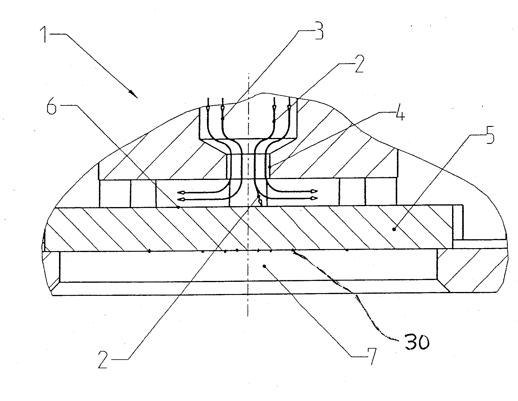
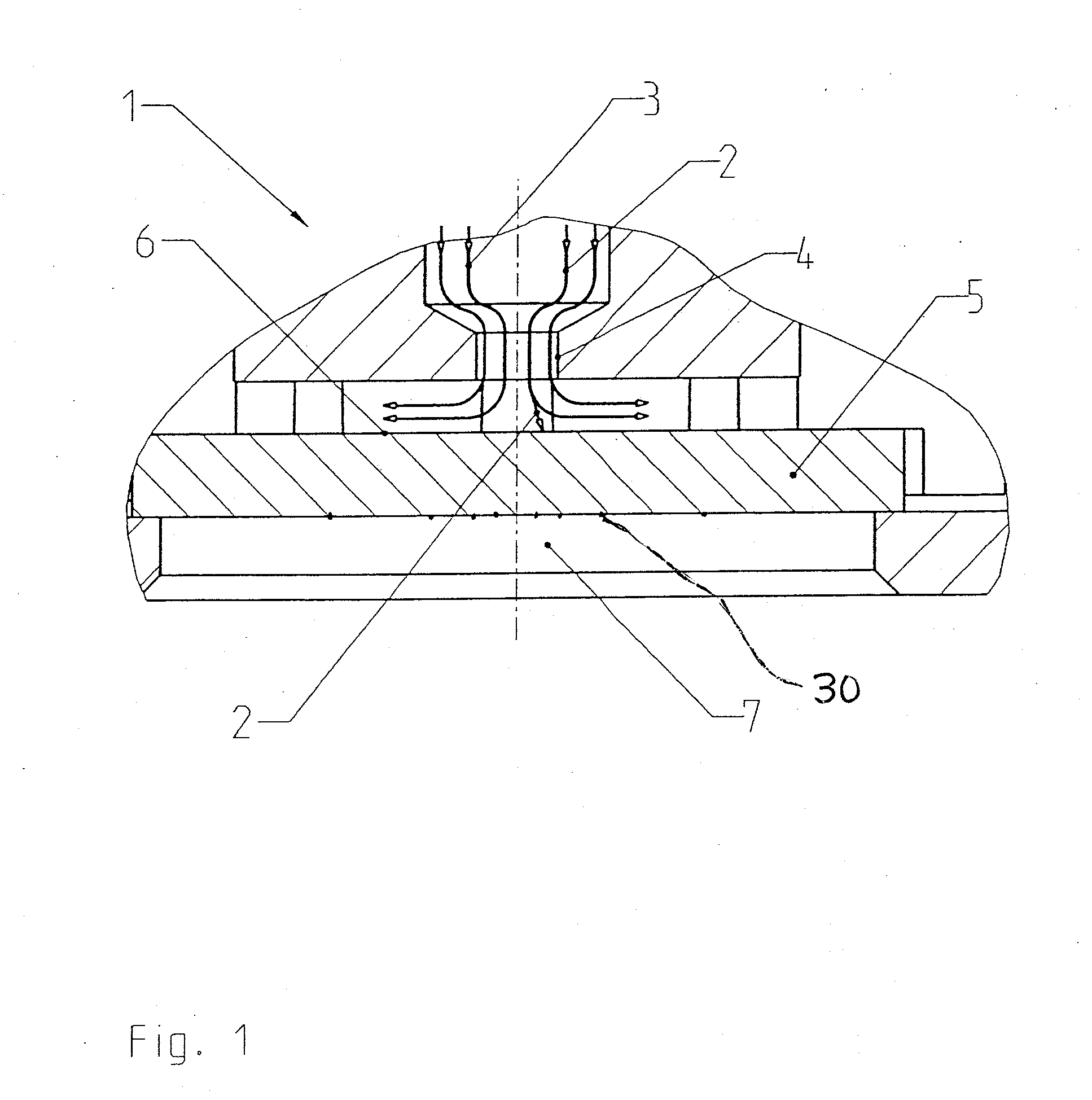
[0033]Referring to the drawings in particular, FIG. 1 schematically illustrates the design of an impactor 1 for the selective measurement of the quantity of oil mist in a gas to be tested. The gas 3, which is loaded with oil particles 2 and is coming from a gas source, not shown, flows through a micronozzle 4 and is deflected at a transparent baffle plate 5 at right angles to the direction in which it enters. Because of the abruptly changing direction of flow, the oil particles 2 are no longer able to follow the flow and are deposited on an absorbent material 6 on the baffle plate 5. The oil particles that impact the baffle plate 5 are collected on the material 6. An oil spot, whose size is perceptible via a window (opening) 7, is now formed on the material 6. The diameter of the oil spot is an indicator of the quantity of deposited oil aerosol. This may be observed based on a scale 30 perceptible via a window (opening) 7 with the plate 5 being glass such as frosted glass.

[0034]When...


PUM

PropertyMeasurementUnit
concentrationaaaaaaaaaa
diameteraaaaaaaaaa

Abstract

A device for the selective determination of the quantity of oil mist includes an impactor (1) with a micronozzle (4) for dispensing a predetermined volume of a gas to be tested, a baffle plate (5) arranged downstream of the micronozzle (4) for depositing oil particles. A window (7) is provided on the side of the baffle plate (5) facing away from the micronozzle (4).

Description

CROSS REFERENCE TO RELATED APPLICATIONS[0001]This application claims the benefit of priority under 35 U.S.C. §119 of German Patent Application DE 10 2006 023 714.5 filed May 19, 2006, the entire contents of which are incorporated herein by reference.FIELD OF THE INVENTION[0002]The present invention pertains to a device and to a method for the selective determination of the quantity of oil mist.BACKGROUND OF THE INVENTION[0003]A gas detector tube for determining the quantity of oil mist in a gas sample has become known from DE 32 23 742 C2. A certain test gas volume is first drawn by means of a pump through the gas detector tube and the oil mist present in the test gas is deposited on a filter within the gas detector tube. An ampule containing sulfuric acid is then pierced, as a result of which the oil in the filter is dissolved and rinsed into a display layer via a distributor layer. A color display, which is proportional to the quantity of the oil mist filtered out of the test gas,...

Claims


Application Information

Patent Timeline
22 Nov 2007
Publication
US20070266769A1
IPC
G01N33/28; G01N1/40; G01N27/22
CPC
G01N2015/0261; G01N15/0255; G01N15/0606; G01N21/00; G01N31/02; G01N33/0004; G01N33/0036
Inventors
LUEBBERT, CHRISTIAN; HEYER, HARALD