
Method and Mechanism for Increasing Critical Speed in Rotating Disks and Reducing Kerf at High Speeds in Saw Blades

a technology of rotating disks and critical speed, which is applied in the direction of metal sawing devices, sawing devices, sawing apparatus, etc., can solve the problems of lowering the critical speed of the blade, large transverse deflection, and blade failure, and achieve the effect of increasing the critical speed of the rotating disk

Inactive Publication Date: 2007-11-22
MCGILL UNIV
View PDF1 Cites 10 Cited by
  • Summary
  • Abstract
  • Description
  • Claims
  • Application Information

AI Technical Summary

Benefits of technology

[0009] Furthermore, there is provided a disk having an increased critical speed of rotation. The disk comprises a plurality of spaced slits machined in a periphery of the disk, each of the slits comprising a pair of opposed slit edges extending from the disk periphery towards a disk axis of rotation, and for each of the slits, a temperature sensitive insert fastened to the disk and spanning the slit. When an insert temperature exceeds a predetermined temperature, the insert contracts thereby reducing a distance between the pair of opposed slit edges.
[0010] Additionally, there is provided a method for reducing the kerf of a saw blade at high speeds, the blade having a serrated edge and a blade temperature which varies in relation to the distance from the serrated edge. The method comprises the steps of providing a blade, and attaching at least one insert to the blade, the at least one insert exerting a tensile stress on the blade when a temperature of the at least one insert reaches a predetermined temperature, the exerted tensile stress opposite to a tensile stress induced in the blade by the varying blade temperature.

Problems solved by technology

When rotated at speeds closing in on the critical speed, the saw blade becomes unstable, leading to large transverse deflections and even blade failure.
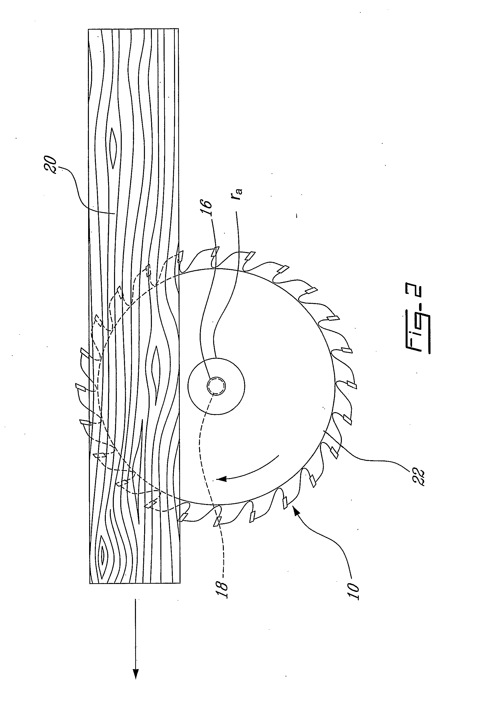
Additionally, friction between the blade and timber causes the temperature at the periphery of the saw blade to increase, which in turn causes a temperature gradient to be set up from the inside to the outside of the blade, thereby lowering the blade's critical speed.
As saws with thinner blades are typically more unstable than thicker blades, the speed at which the thinner blades can be operated can be significantly lower than that of the thicker blades.
Other methods include heating the blade at its centre, decreasing the temperature gradient and to some degree its adverse effect on critical speed.

Method used


Image

  • Method and Mechanism for Increasing Critical Speed in Rotating Disks and Reducing Kerf at High Speeds in Saw Blades
  • Method and Mechanism for Increasing Critical Speed in Rotating Disks and Reducing Kerf at High Speeds in Saw Blades
  • Method and Mechanism for Increasing Critical Speed in Rotating Disks and Reducing Kerf at High Speeds in Saw Blades

Examples


first embodiment

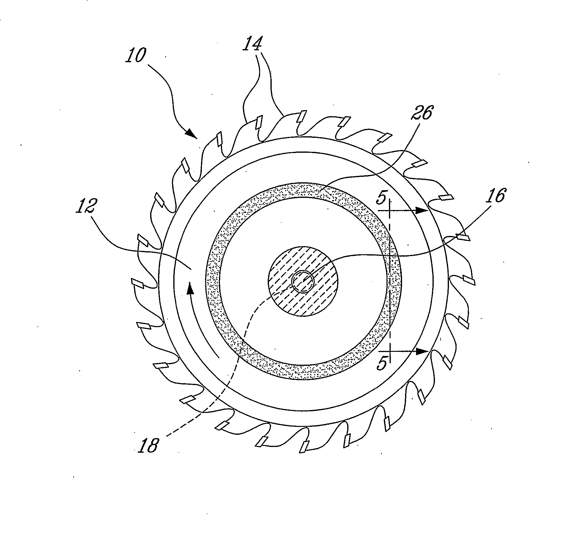
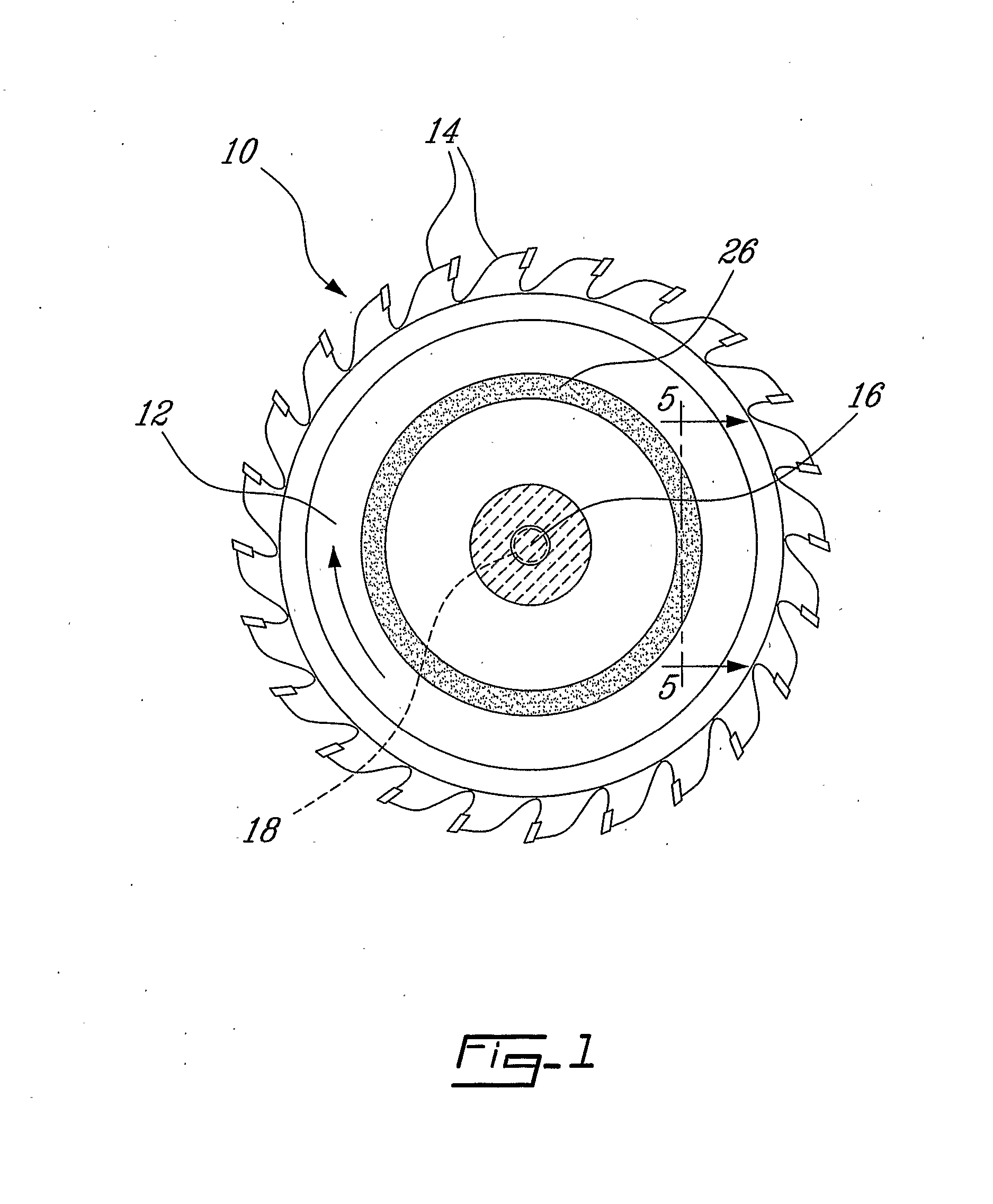
[0045] Referring now to FIGS. 6A and 6B, in a first embodiment, the inserts 26 and depressions 28, 30 are generally rectangular in shape. The inserts 26 are attached to the blade 10 towards the outer edges 36, 38 via a series of fasteners as in 40, for example rivets or screws or the like. The inserts 26 straddle a slit 42 in the blade 10, the slit 42 illustratively in a direction radial to the axis of rotation. The inserts 26 are heat treated such that when in the austenite phase the outer edges 36, 38 are brought closer together. Therefore, as the periphery 22 of the blade 10 is heated, forces are brought to bear on the blade between the fasteners as in 40 (in the direction indicated by the arrows) and the gap of the radial slit 42 is reduced, thereby reducing the hoop stresses introduced by the peripheral heating.

second embodiment

[0046] Referring now to FIGS. 7A and 7B, in a second embodiment, the inserts 26 and depressions as in 28, 30 are annular in shape. One or more inserts as in 26 are press fit into the annular depressions as in 28, 30. The inserts are heat treated such that when in the austenite phase they expand in a radial direction outward. Therefore, as the periphery 22 of the blade 10 is heated, forces in a outward radial direction (as indicated by the arrows arrange around the periphery 22) are introduced, thereby countering the hoop stresses introduced by the peripheral heating. Of note is that although the present invention has been discussed hereinabove in regards to blades or disks where the periphery has a higher temperature than centre of the blade or disk, the present invention may also be applied to increase the stability of uniformly heated blades or disks, or alternatively for pretensioning disks which operate at room or lower temperatures. For example, the insert(s) 26 as described he...


PUM

PropertyMeasurementUnit
temperatureaaaaaaaaaa
thickaaaaaaaaaa
thickaaaaaaaaaa

Abstract

There is provided a method for increasing the critical speed of a rotating disk and disk using same. The method comprises the steps of providing a disk and fastening at least one heat sensitive insert to the disk. The insert exerts a tensile stress on the disk when an insert temperature exceeds a predetermined temperature. The disk could be a saw blade. Also, there is provided a saw blade and method having a reduced kerf at high speeds, the blade having a serrated cutting edge. The blade comprises at least one insert attached to the blade, the at least one insert exerting a tensile stress on the blade when an insert temperature reaches a predetermined temperature, the exerted tensile stresses opposite to those induced by the blade temperature.

Description

BACKGROUND OF THE INVENTION [0001] In the production of lumber, appreciable amounts of timber are converted into sawdust by the saw blade. As most saw dust is waste and is subsequently discarded into landfills or incinerated, reduction in the amount of sawdust provides for an improved usage of the timber. Additionally, trends such as environmental constraints on timber harvesting, smaller logs and an increased demand for wood products have driven the lumber industry to seek new ways to improve the efficiency of their production processes. [0002] The amount of sawdust is determined by the width of the cut, or kerf, made by the teeth of the saw blade in the timber. Typical circular sawmill converts 50% of a log into primary lumber with the recovery rate of band mills being somewhat higher at about 57%. Losses due to saw kerf average about 20% for a circular sawmill and as low as 12% for high production band mills. [0003] The saw kerf has a significant impact on the efficiency of the c...

Claims


Application Information

Patent Timeline
Patent Type & Authority Applications(United States)
IPC IPC(8): B27G19/02B27B33/08B23D59/00B23D61/02C22C14/00C22C19/00
CPCB23D61/026B23D59/001Y10T83/04Y10T83/9319
Inventor RADZISZEWSKI, PETERPOIRIER, JULIEN
Owner MCGILL UNIV
Learn More