AI technical title is built by Patsnap AI team. It summarizes the technical point description of the patent document.
a work table and multi-position technology, applied in the field of furniture, can solve the problems of compulsion of users, undesirable weight and considerable extra cost, and undesirable jack-actuation for many users
Inactive Publication Date: 2007-11-22
CARRABBA STEPHEN
View PDF17 Cites 47 Cited by
Summary
Abstract
Description
Claims
Application Information
AI Technical Summary
This helps you quickly interpret patents by identifying the three key elements:
Problems solved by technology
Method used
Benefits of technology
Benefits of technology
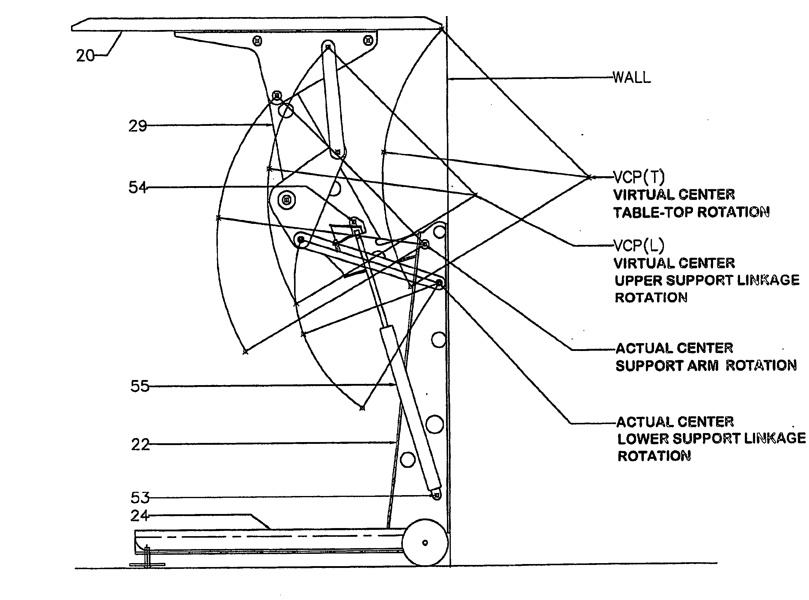
[0042] The apparatus is a unique combination of cooperating support arms and linkages that maintain the work surface in a horizontal position throughout its range of motion. The unique linkage provides better strength geometry than other linkage designs and pivots about virtual centers in imaginary space to create a smaller overall form factor that takes up less space in the workplace.
Problems solved by technology
Mechanical and hydraulic jacks have been suggested, but they often compel the user to provide exhausting hand-cranking or careful monitoring of electrical pump controls.
Moreover, such jacks introduce undesirable weight and considerable extra cost, making such jack-actuation undesirable for many users.
Method used
Image
Click on the blue label to locate the original text in one second.
Reading with bidirectional positioning of images and text.
Examples
first and second embodiments
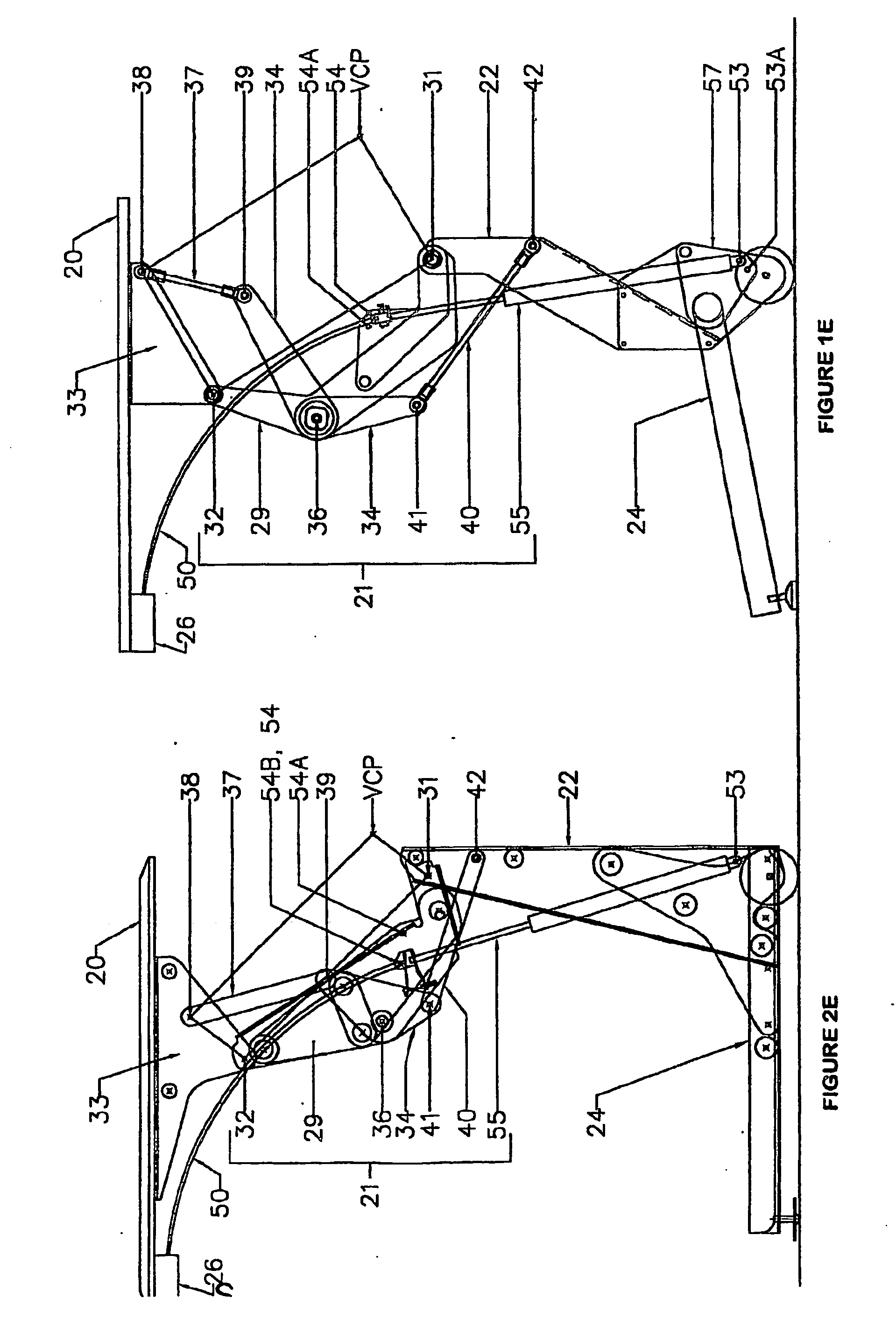
[0045] Comparison of FIGS. 1E and 2E shows that tabletop 20 is supported in both the first and the second preferred embodiments by a pivoted linkage 21, which itself is pivotally mounted on column 22, upstanding from base 24.
[0046] In each embodiment a gas springpiston-cylinder assembly 55 has its ends pivotally connected to column 22 and to linkage 21.
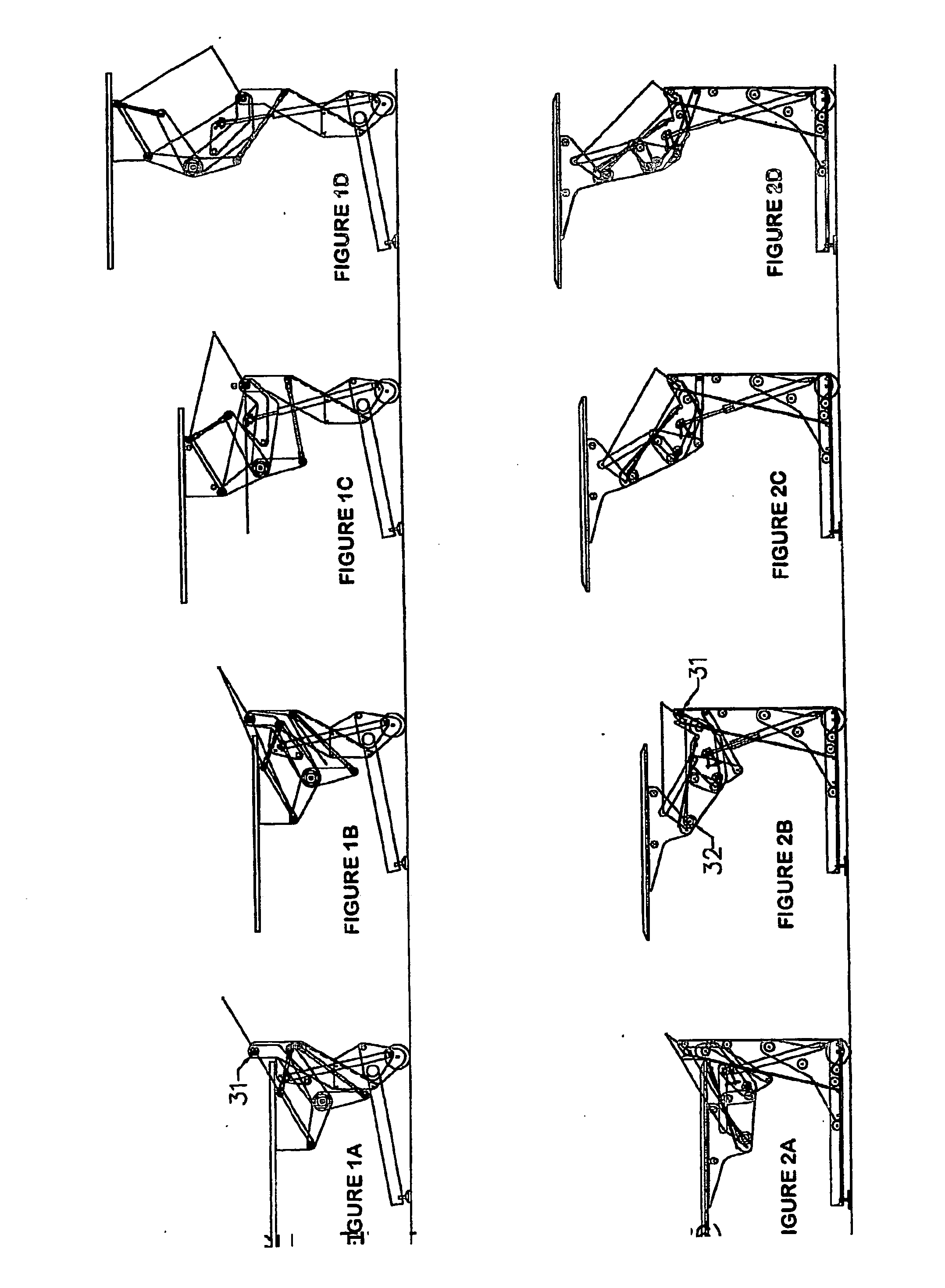
[0047] The pivotally connected components forming linkage 21 are very similar in both the first and the second preferred embodiments. This is confirmed by comparing the exploded views of FIG. 1F and FIG. 2F, where the various comparable components are arrayed side by side in these two FIGURES. The pivoted interconnections of each of these linkage components with the next is clearly shown in the assembled views of FIGS. 1E and 2E, and their articulated movement is shown in FIGS. 3A-3F.
[0048] Thus, for the first embodiment, a central member is the cantilever arm 29, shown to be U-shaped in FIG. 1F, having rear pivot point 31, joinin...
second embodiment
Pivoted Components of Second Embodiment
[0055] As shown in FIGS. 2E and 2F, the same components are connected in much the same fashion in the second preferred embodiment as they are in the first preferred embodiment, and the pivoting articulation of these components of linkage 21 is shown in the six successive diagrams of FIGS. 4A through 4F, and in FIGS. 6, 7 and 8.
[0056] Accordingly, the foregoing description of the linkage components of the first preferred embodiment is equally applicable to those of the second, and the corresponding components and pivot points have been given the same reference numerals in the FIGURES.
[0057] Cantilever arm 29 is V-shaped and bell crank 34 is generally triangular, but these do not change their function or cooperation.
[0058] When the gas spring piston-cylinder 55 is ideally pressurized for the total weight of the tabletop, opening the control valve 48 will allow the tabletop to “float” with minimum han...
PUM
Abstract
A compact height adjustable work station utilizes a unique combination of support arms and linkages to achieve greater strength and a greater range of tabletop height adjustment from a smaller form factor than is found anywhere in the industry. The method for adjusting the work surface height is user operated and pressure assisted whereby the user requires a minimal effort to physically lift or lower the work surface to the desired tabletop height. The pressure assist can be variably located to counterbalance different tabletop weights. For automatic counterbalancing, an elongated extensible gas springpiston-cylinder is adapted to be locked in any of its continuous range of infinite adjusted positions. Manual unclamping frees the counterbalancing gas spring for readily changed, manual tabletop height level adjustment. A mid-range level or a high tabletop level may be achieved, adjusted by unclamping and minimum manual force.
Description
FIELD OF THE INVENTION [0001] This invention relates generally to tables in the furniture field and, more specifically, to ergonomically designed office and industrial work stations. [0002] The invention provides height adjustable multiple-position worktable levels producing ergonomic benefits to workers of various size while they are performing various work tasks. Research has shown that adapting a work station to the reach and viewing needs of a worker increases productivity and reduces the occurrence of injury. [0003] The preferred embodiments of the invention are extremely economical to manufacture and readily operated by the user to achieve prompt and efficient movement of the tabletop between an infinite number of different level positions. [0004] Mechanical and hydraulic jacks have been suggested, but they often compel the user to provide exhausting hand-cranking or careful monitoring of electrical pump controls. Moreover, such jacks introduce undesirable weight and considera...
Claims
Application Information
Patent Timeline
Application Date:The date an application was filed.
Publication Date:The date a patent or application was officially published.
First Publication Date:The earliest publication date of a patent with the same application number.
Issue Date:Publication date of the patent grant document.
PCT Entry Date:The Entry date of PCT National Phase.
Estimated Expiry Date:The statutory expiry date of a patent right according to the Patent Law, and it is the longest term of protection that the patent right can achieve without the termination of the patent right due to other reasons(Term extension factor has been taken into account ).
Invalid Date:Actual expiry date is based on effective date or publication date of legal transaction data of invalid patent.
Patent Type & AuthorityApplications(United States)

