
Intake accelerator for an engine

a technology of an intake accelerator and an engine, which is applied in the direction of combustion engines, charge feed systems, fuel re-atomisation/homogenisation, etc., can solve the problems of easy encounter of limitation in use materials and the reduction of the original expected effect of the accelerator vortex, and achieves the effect of reducing the vortex effect and being easy to produ

Inactive Publication Date: 2007-11-22
YANG CHUNG YU
View PDF5 Cites 12 Cited by
  • Summary
  • Abstract
  • Description
  • Claims
  • Application Information

AI Technical Summary

Benefits of technology

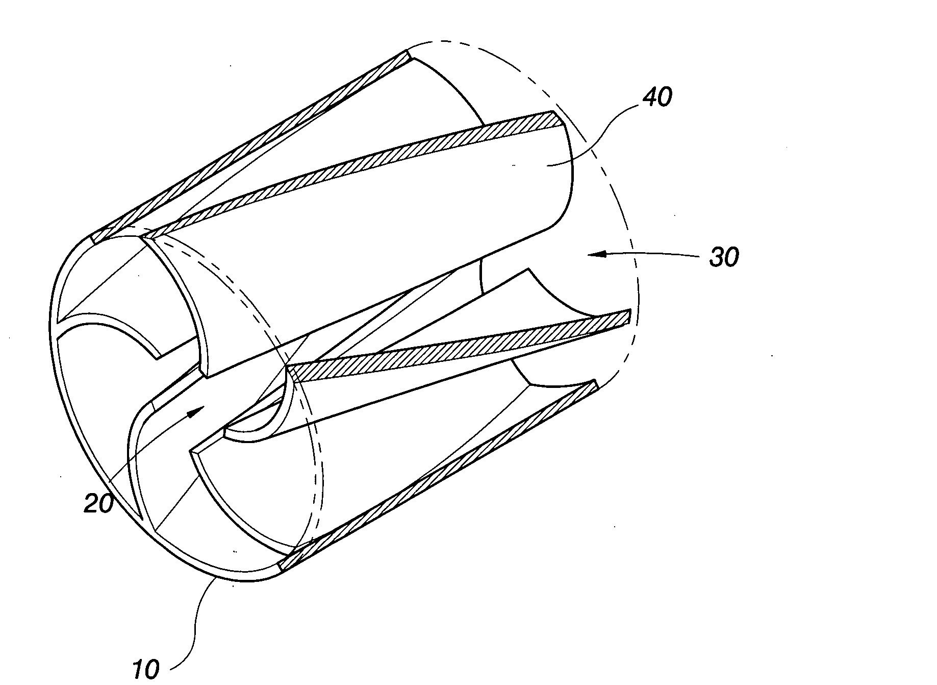
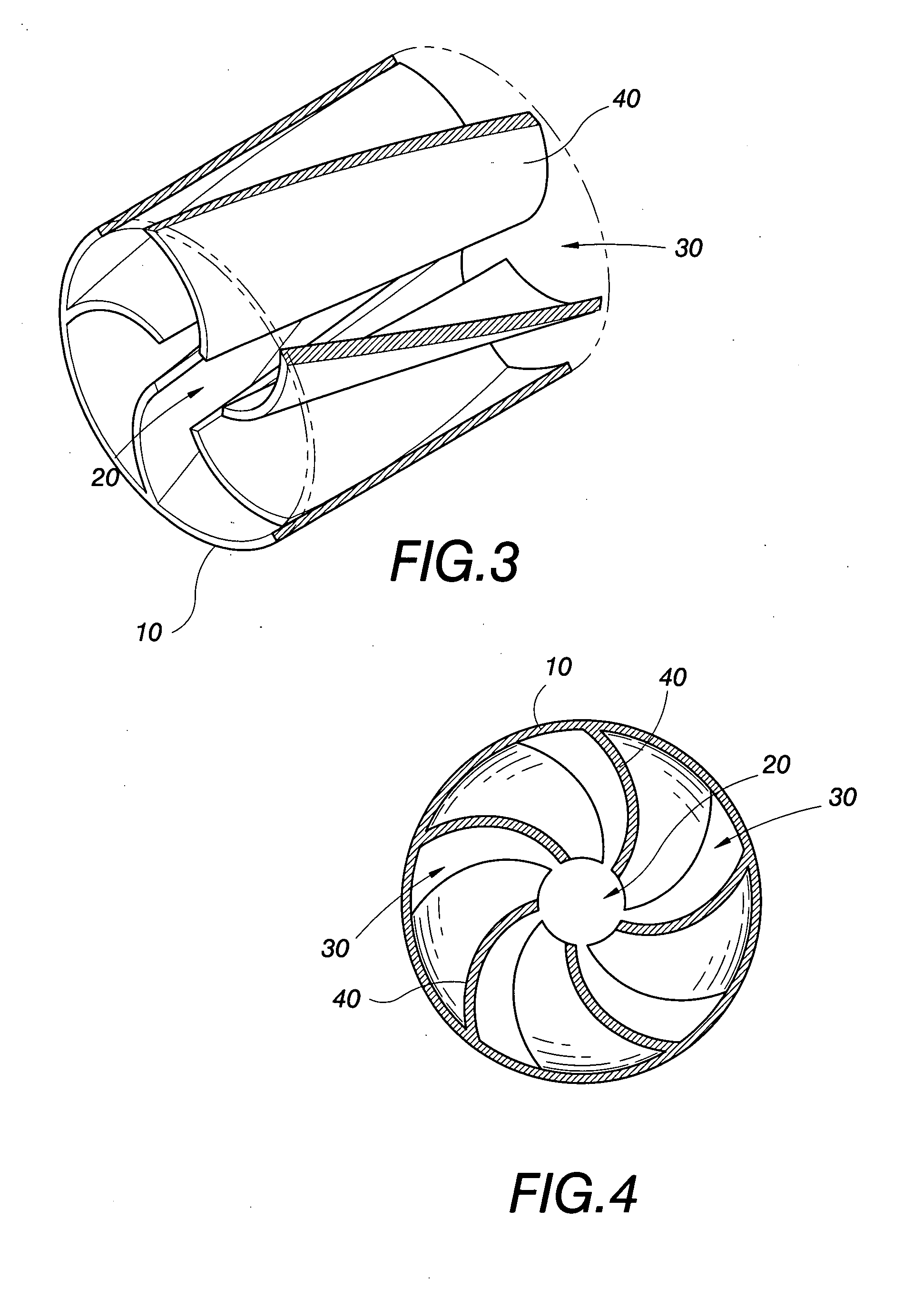
[0010]The accelerator of the present invention is provided in the main body thereof with a plurality of vortex guiding blades extending from the periphery to the center of the wall of a pipe, thereby a vortex passage is formed between every two neighboring ones of the vortex guiding blades; these vortex passages circle in the interior of the main body of the accelerator, so that after air flow enters the main body of the accelerator, it is guided to generate a plurality of vortexes running in the same direction, this can increase flow of the air of the vortexes.
[0018]2. There is no problem of requiring further air flow integration after air flow leaves the accelerator to lower the vortex effect.

Problems solved by technology

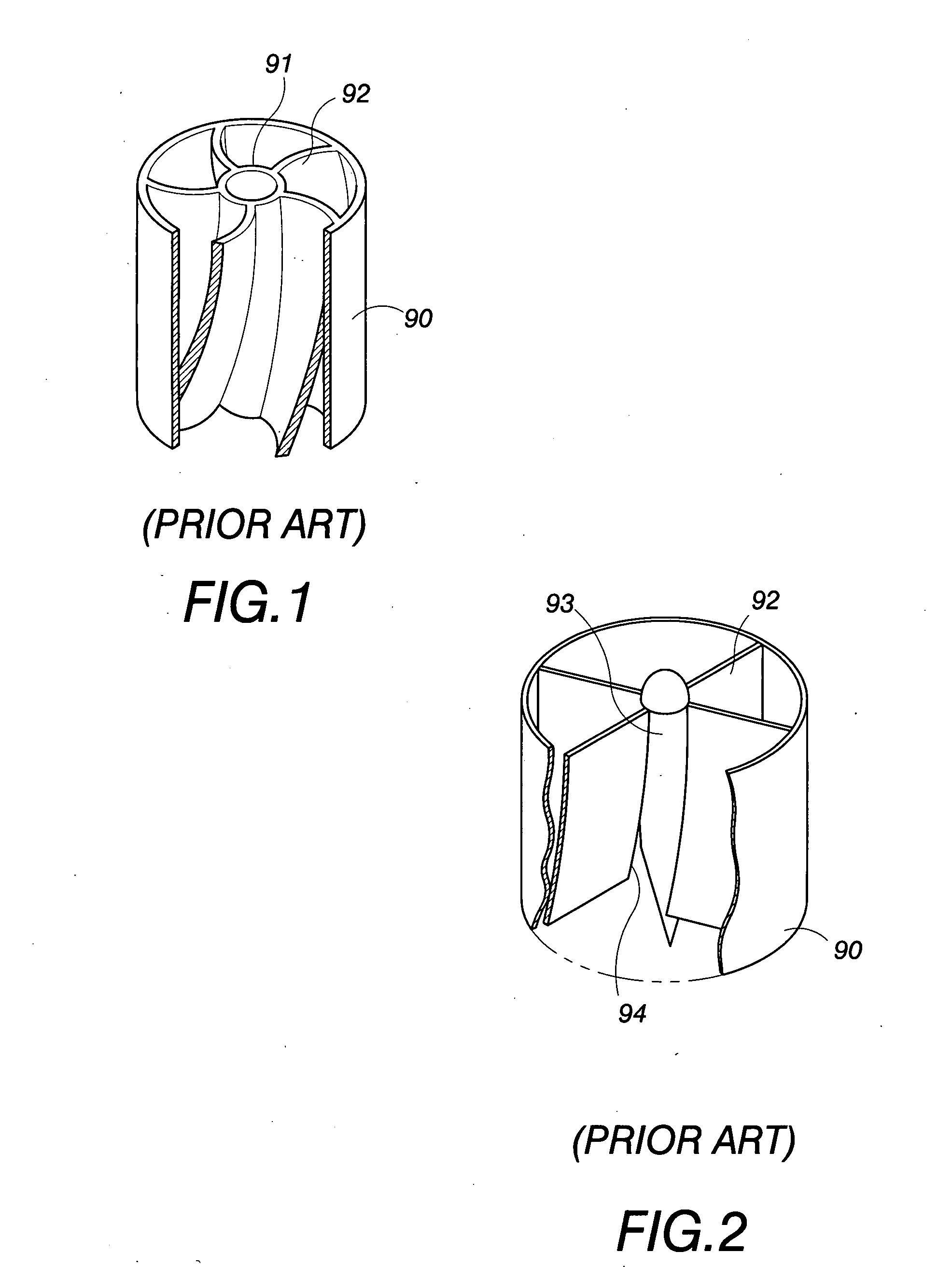
However, such a technical means is subjected to generating partial turbulence by integrating of the straight line air flow and the vortical air flows when they leave the accelerator; thereby the original expected effect of vortex of the accelerator is largely reduced, and even vibrating and noises may be created by this.
However, although such a technical means can make smooth of the integration of the plural vortical air flows, the structure of the tailing end of the central guiding post 93 and the end openings 94 are all structures difficult to process in the industry, limitation in use material can be easily encountered, for instance: it is hard to integrally injection form them using plastic, and thereby it is often that metallic material can be needed for producing and assembling the round pipe 90, the arched blades 92 and the central guiding post 93; and further it needs related positioning and connecting processes for assembling, such as the case of U.S. Pat. No. 6,158,412.

Method used


Image

  • Intake accelerator for an engine
  • Intake accelerator for an engine
  • Intake accelerator for an engine

Examples


Embodiment Construction

[0036]Referring to the first embodiment of the present invention shown in FIGS. 3, 4, wherein the main body 10 of an accelerator is in the shape of a cylinder, the main body 10 of the accelerator is provided with a central passage 20 and a plurality of vortex passages 30.

[0037]The central passage 20 is extended axially through the center of the main body 10 of the accelerator; the vortex passages 30 circle in the interior of the main body 10 of the accelerator and are communicated with the central passage 20. As is depicted in the drawings, the central passage 20 and the vortex passages 30 are formed from a plurality of vortex guiding blades 40 extending from the periphery of the wall of a pipe to the center thereof; wherein the vortex guiding blades 40 are kept appropriate distances from each other near the central area of the main body 10 of the accelerator to form the central passage 20; and a vortex passage 30 is formed between every two neighboring ones of the vortex guiding bl...


PUM


Abstract

An intake accelerator for an engine, the intake accelerator is installed in the front end of a pipe line at an intake of an engine to increase the efficiency of the engine. The main body of the accelerator is provided therein with a plurality of vortex guiding blades extending from a periphery to the center of the wall of a pipe, thereby a vortex passage is formed between every two neighboring ones of the vortex guiding blades; these vortex passages circle in the interior of the main body of the accelerator, so that after air flow enters the main body of the accelerator, it is guided to generate a plurality of vortexes running in the same direction, this can increase the air flow of the vortexes.

Description

BACKGROUND OF THE INVENTION[0001]1. Field of the Invention[0002]The present invention relates to a vortex generating structure, and especially to an intake accelerator for an engine for vortex generating, the intake accelerator is installed in the front end of a pipe line at an intake of an engine to increase the efficiency of the engine.[0003]2. Description of the Prior Art[0004]An engine is also called generally as an internal combustion engine; its principle of action is to lead fuel and air into a cylinder of the engine to generate therein violent combustion to releasing very much energy to be converted into power for running a machine.[0005]The higher the rotating rate of the engine is, the larger the amount of air led into the cylinder in a unit time can be obtained; for the purpose of getting better intake effect when the engine is running with high rate, manufacturers studied and developed an accelerator to be added in the front end of a pipe line at an intake of the engine ...

Claims


Application Information

Patent Timeline
Patent Type & Authority Applications(United States)
IPC IPC(8): F02B31/00F02M29/00
CPCF02M29/06
Inventor YANG, CHUNG-YU
Owner YANG CHUNG YU
Learn More