Device for generating acoustic and/or vibration energy for heat exchanger tubes

a technology of acoustic and/or vibration energy and heat exchanger tube, which is applied in the field of mitigation of fouling in heat exchangers, can solve the problems of reducing the effectiveness of heat exchangers, affecting equipment operation, and low thermal conductivity of fouling layers, so as to achieve the effect of reducing the surface fouling

Inactive Publication Date: 2007-11-22
EXXON RES & ENG CO
View PDF10 Cites 30 Cited by
  • Summary
  • Abstract
  • Description
  • Claims
  • Application Information

AI Technical Summary

Benefits of technology

The technical effect of this patent relates to creating a tool that generates vibration to produce shear waves in liquid near a hot surface to prevent it from becoming too dirty with buildup.

Problems solved by technology

The technical problem addressed in this patent text is how to reduce or eliminate fouling (the buildup of material) on the surfaces of heat exchangers used in petroleum processing, without requiring frequent and expensive shutdowns for cleaning. Existing solutions involve either replacing parts or adding new components to the heat exchanger, making it difficult to adapt to existing facilities. A method is needed to effectively treat existing equipment while keeping it online and minimizing downtime.

Method used


Image

  • Device for generating acoustic and/or vibration energy for heat exchanger tubes
  • Device for generating acoustic and/or vibration energy for heat exchanger tubes
  • Device for generating acoustic and/or vibration energy for heat exchanger tubes

Examples


Embodiment Construction

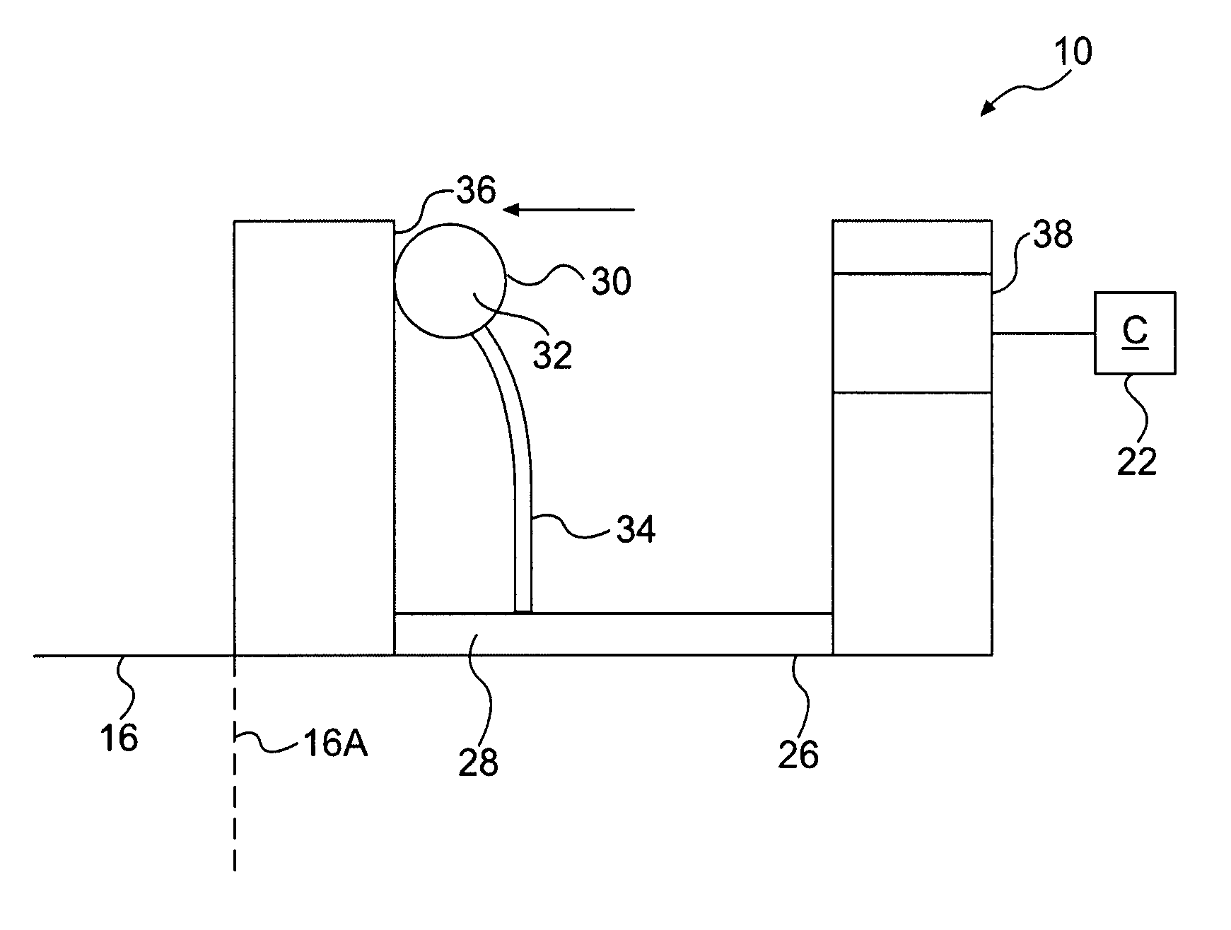
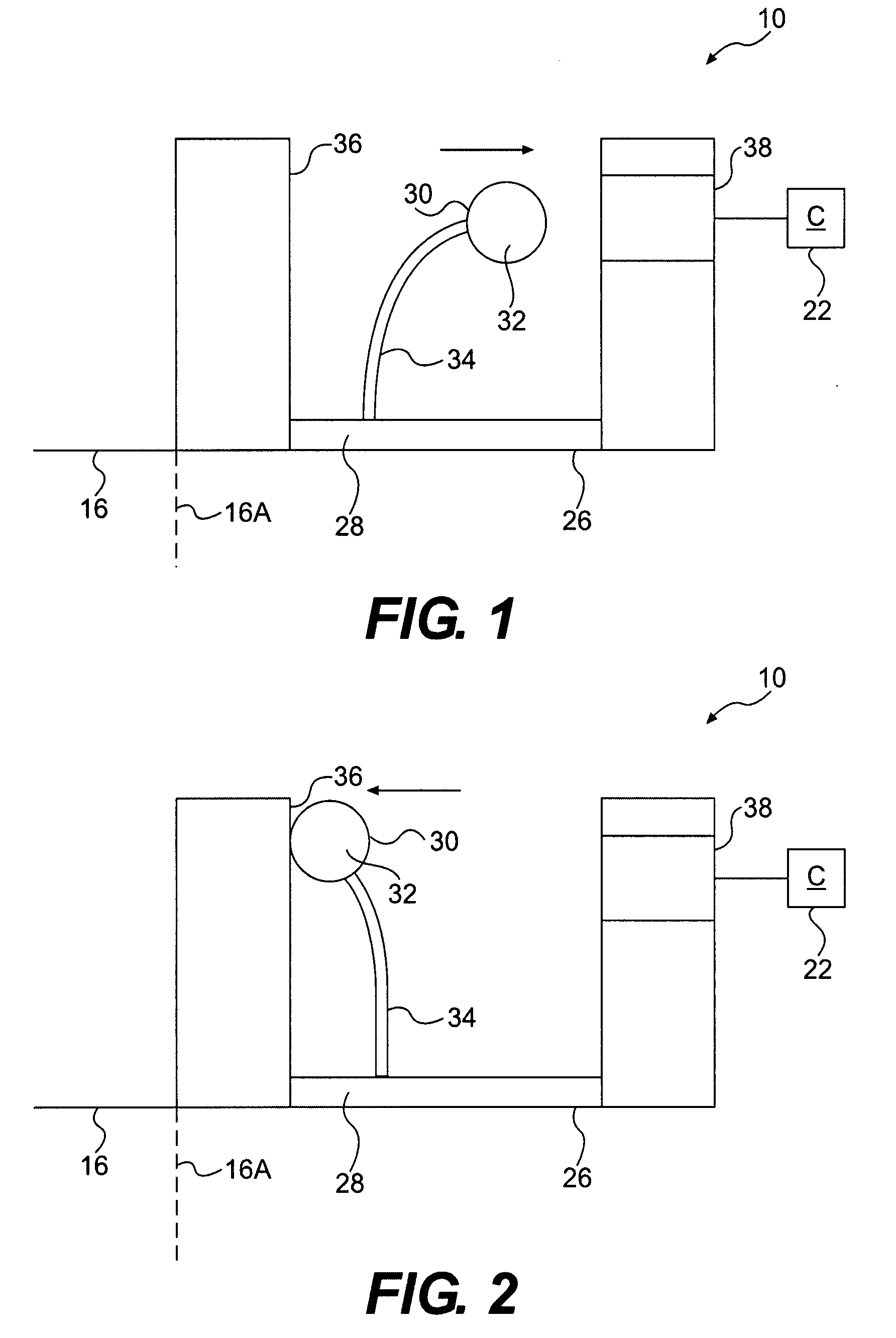
[0033]This invention is directed to a device for mitigating fouling in heat exchangers, in general. In a preferred use, the device is applied to heat exchangers used in refining processes, such as in refineries or petrochemical processing plants. Such processing generally involves whole crude oils, blends and fractions, which will be referred to collectively herein merely as crude oils for purposes of simplicity. The invention is particularly suited for retrofitting existing plants so that the process may be used in existing heat exchangers, especially while the heat exchanger is on line and in use. Of course, it is possible to apply the invention to other processing facilities and heat exchangers, particularly those that are susceptible to fouling in a similar manner as experienced during refining processes and are inconvenient to take off line for repair and cleaning.

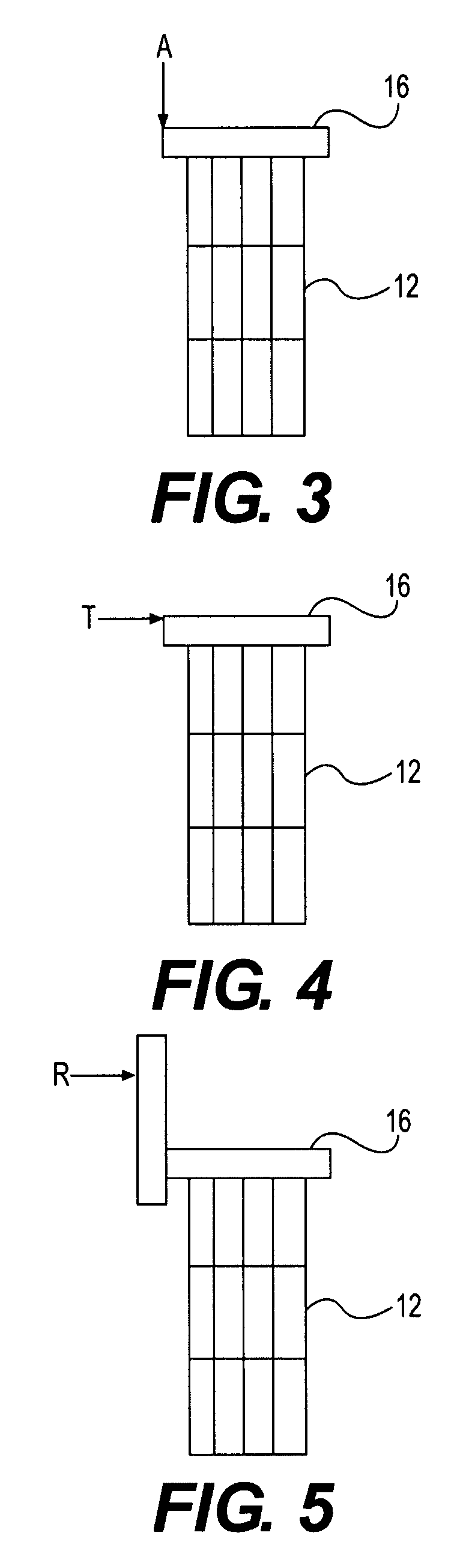
[0034]While this invention can be used in existing systems, it is also possible to initially manufacture a heat exc...


PUM


Abstract

A device is coupled to a heat exchanger for mitigating fouling by applying a mechanical force to a fixed heat exchanger to excite a vibration in the heat exchange surface and produce shear waves in the fluid adjacent the heat exchange surface while the heat exchanger is in operation. An electromagnetic driven impulse device induces vibration onto heat exchanger tubes and/or an acoustic wave through the liquid service fluid to reduce fouling. The device can be mounted directly onto the outer part or piping and produces acoustical/vibrational modes onto the tube or near the surface of tubes.

Description


Claims


Application Information

Patent Timeline
Owner EXXON RES & ENG CO
Why Eureka
Try Eureka