Diagnostic control device for a hybrid vehicle

a control device and hybrid technology, applied in the direction of gas pressure propulsion mounting, combustion air/fuel air treatment, fluid tightness measurement, etc., can solve the problem of requiring a long suction time, failure diagnostic control is more prone to reset, and the diagnosis time is delayed in the evaporation purge system. , to achieve the effect of shortening the failure diagnostic tim

Inactive Publication Date: 2007-11-22
SUBARU CORP
View PDF5 Cites 20 Cited by
  • Summary
  • Abstract
  • Description
  • Claims
  • Application Information

AI Technical Summary

Benefits of technology

[0013]According to the present invention, when introducing negative pressure in the inlet pipe into a vapor path, engine load is reduced by the driving of an electric motor to

Problems solved by technology

It is difficult for such a small engine or a high expansion ratio engine to create a large negative pressure in the inlet pipe due to their small intake air volume, which causes a delay in diagnosis time in their evaporation purge systems.
In other words, it is necessary to introduce negative pressure in the inlet pipe

Method used


Image

  • Diagnostic control device for a hybrid vehicle
  • Diagnostic control device for a hybrid vehicle
  • Diagnostic control device for a hybrid vehicle

Examples


Embodiment Construction

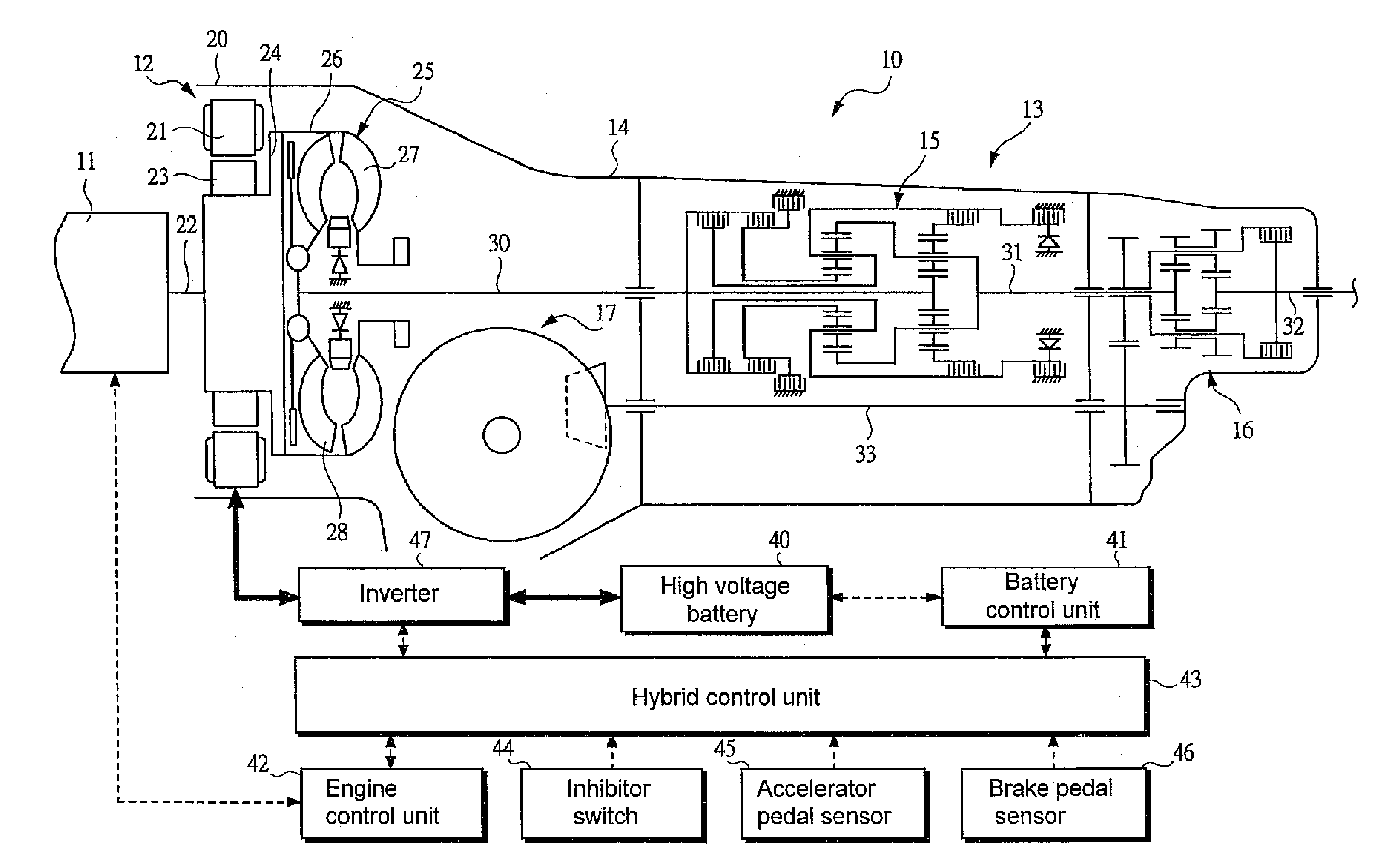
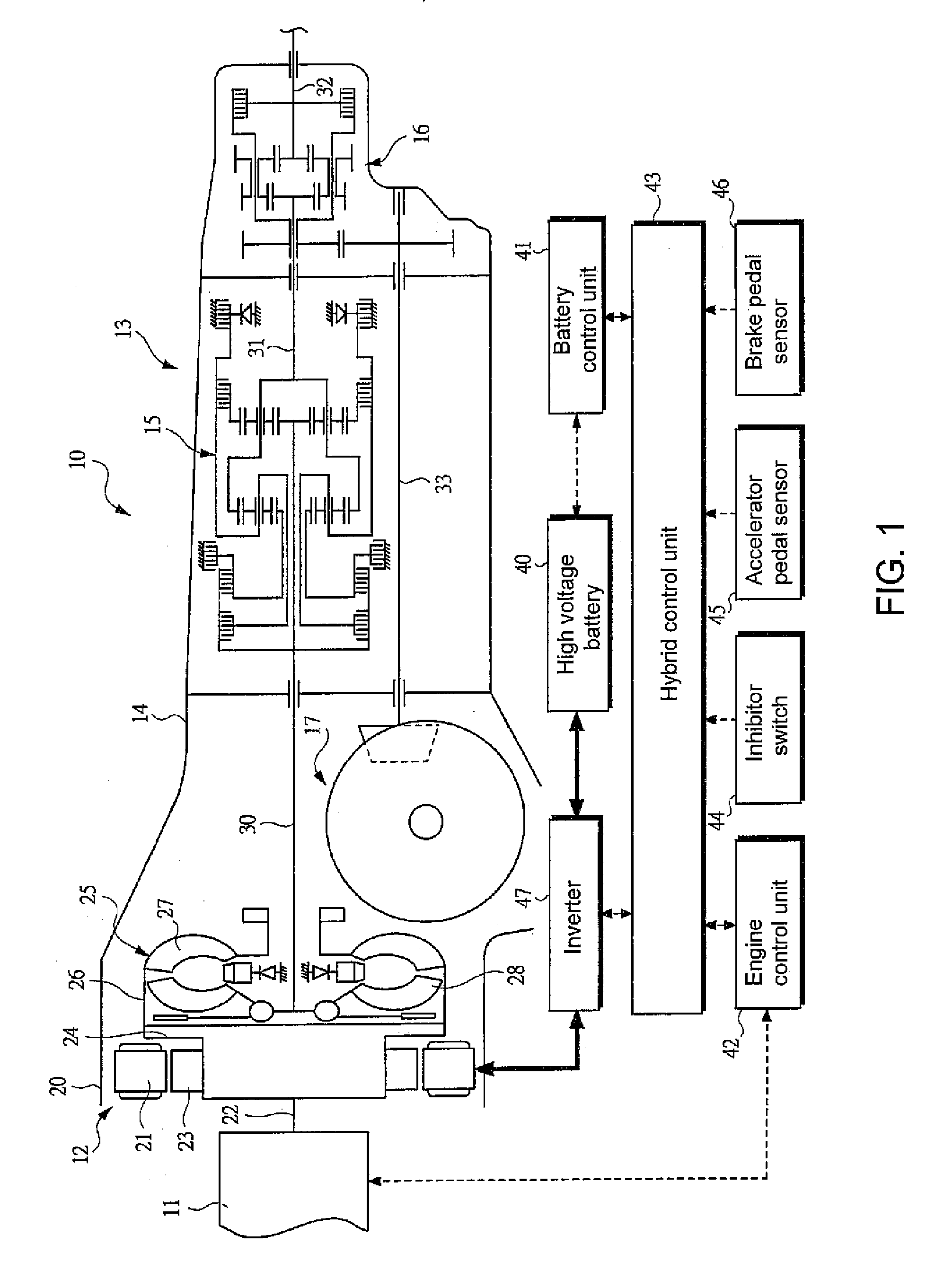
[0014]Hereafter embodiments of the present invention are explained in detail, referring to the attached figures. FIG. 1 is a skeleton diagram showing a power unit 10 that is installed in a hybrid vehicle. As shown in FIG. 1, the power unit 10 is equipped with an engine 11 and a motor generator (electric motor) 12 as power sources, and a transmission 13 is installed on the posterior side of the motor generator 12. The power outputted from the engine 11 and motor generator 12 is distributed to each of driving wheels via a plurality of differential mechanisms 16 and 17 after shifting gears via a gear mechanism 15 which is incorporated in a mission case 14.

[0015]The illustrated power unit 10 is a parallel-mode power unit, in which the engine 11 is operated as the main source of power for driving, and as a supplemental power source at times of starting and acceleration, the motor generator 12 is operated. In addition, during a deceleration or driving at a constant-speed, by making the mo...


PUM


Abstract

A diagnostic control device for a hybrid vehicle is provided for shortening the time required for a failure diagnosis of an evaporation purge system. After introducing the inlet-pipe's negative pressure into the evaporation purge system 51, the evaporation control unit 52 diagnoses failure states concerning the evaporation purge system 51 such as a leak by detecting changes in inner tank pressure over a prescribed time. In order to shorten such failure diagnosis control time, a motor generator 12 is driven to assist the engine when introducing the inlet-pipe's negative pressure into the evaporation purge system 51. With such assist-driving, it becomes possible to reduce engine load, therefore, the throttle valve 67 of the engine 11 can be controlled to be on the closed side, making it possible to create sufficient inlet-pipe's negative pressure. Through this, the pressure in the evaporation purge system 51 can be decreased quickly, which shortens the time for failure diagnosis in the evaporation purge system 51.

Description

CROSS REFERENCE TO RELATED APPLICATIONS[0001]This application claims priority under 35 U.S.C. 119 based upon Japanese Patent Application Serial No. 2006-141938, filed on May 22, 2006. The entire disclosure of the aforesaid application is incorporated herein by reference.FIELD OF THE INVENTION[0002]This invention relates to a diagnostic control device for a hybrid vehicle having an engine with an electric motor coupled to the engine, and more specifically to an effective technology for performing failure diagnostic control of an evaporation process mechanism that processes fuel vapor.BACKGROUND OF THE INVENTION[0003]In order to appropriately process fuel vapor generated in a fuel tank, an evaporation process mechanism (referred to as an evaporation purge system hereafter) is installed in the fuel system of a vehicle, such that fuel vapor is burned within cylinders. This evaporation purge system contains a canister in which activated carbon is sealed. After being captured by the canis...

Claims


Application Information

Patent Timeline
IPC IPC(8): B60K6/00G01M19/00F02B73/00F02M25/08B60K6/48B60W10/06B60W10/08B60W20/00F02D29/02G01M99/00
CPCB60K6/36B60K6/387B60K6/40B60K6/485Y02T10/6226F02M25/0827F16H3/66G01M3/3263B60K6/547Y02T10/62
Inventor SAITO, YOICHI
Owner SUBARU CORP
Why Eureka
Try Eureka