Apparatus and method for non-contact microfluidic sample manipulation
What is Al technical title?
Al technical title is built by PatSnap Al team. It summarizes the technical point description of the patent document.
a microfluidic and sample technology, applied in the field of microfluidic tools, can solve the problems of contaminating electrochemical reactions and joule heating, large electrical current, and long processing tim
Inactive Publication Date: 2007-11-22
NOTRE DAME DU LAC UNIV OF THE
View PDF6 Cites 10 Cited by
Summary
Abstract
Description
Claims
Application Information
AI Technical Summary
This helps you quickly interpret patents by identifying the three key elements:
Problems solved by technology
Method used
Benefits of technology
Problems solved by technology
A drawback to most electrokinetic tools is that a large electrical current must be passed through the liquid sample to create strong convective electro-osmotic flows (i.e., movement of liquid relative to a stationary charged surface by an applied electric field) and/or to create strong electrophoretic/dielectrophoretic forces that are needed for rapid sample processing.
For most electrode configurations a sufficiently large electrical current will lead to contaminating electrochemical reactions and Joule heating, both of which are highly undesirable.
This is particularly problematic for biological and
Method used
Image
Click on the blue label to locate the original text in one second.
Reading with bidirectional positioning of images and text.
Examples
Embodiment Construction
[0020] The following description of the disclosed embodiment is not intended to limit the scope of the invention to the precise form or forms detailed herein. Instead the following description is intended to be illustrative of the principles of the invention so that others may follow its teachings.
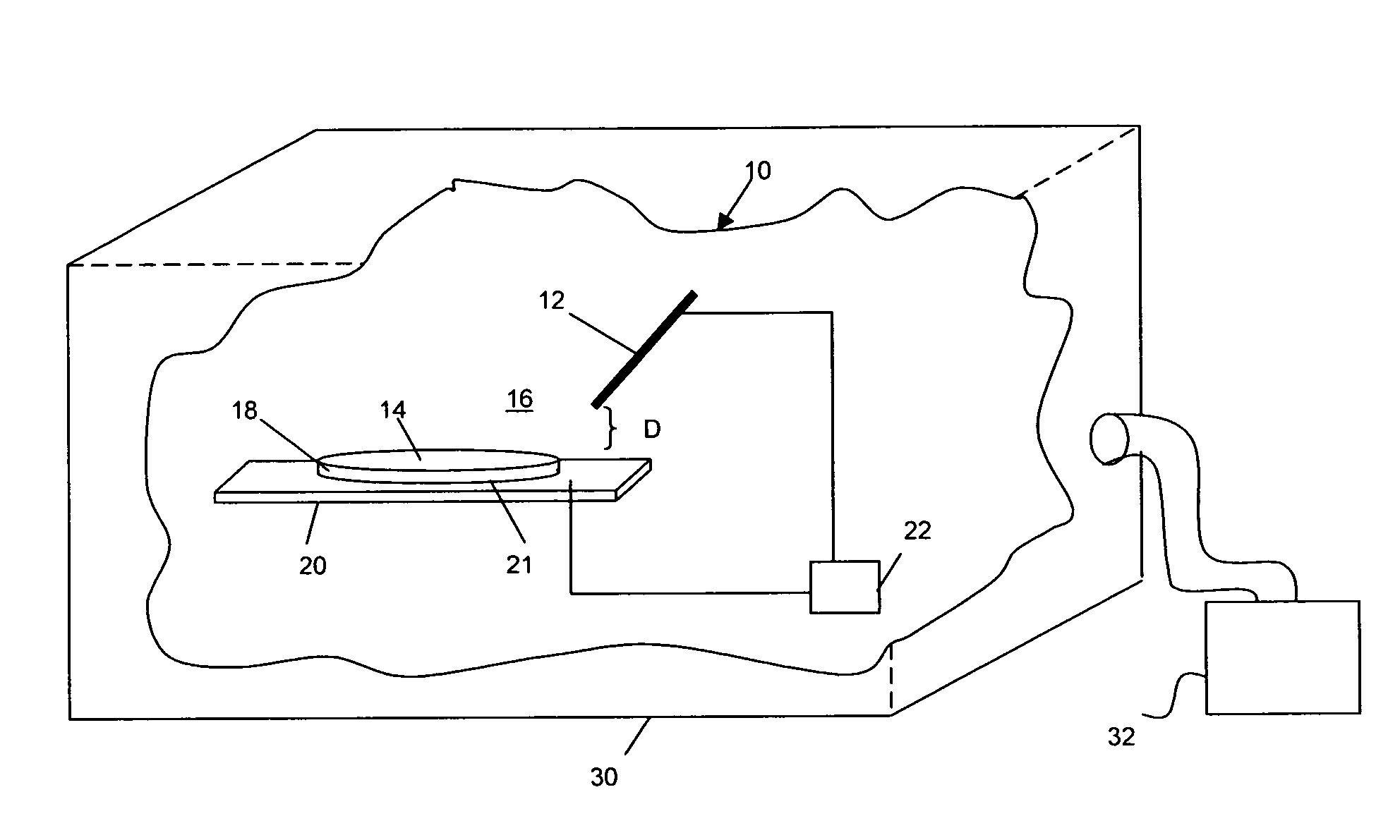
[0021] Referring now to the drawings, FIG. 1 is an illustration of an example microfluidic electro-hydrodynamic apparatus 10, constructed in accordance with the teachings of the present invention. In general, the microfluidic electro-hydrodynamic apparatus 10, may avoid significant Joule heating and contaminating electrochemical reactions by reducing the amount of electrical current that passes through the liquid sample. For instance, by aligning an electrode in the vicinity of the ambient medium / liquid sample interface, but not within the liquid sample, one can rapidly induce a flow that can be used for focusing, mixing, pumping, and / or separating a liquid sample or a component of a liqu...
PUM
Property
Measurement
Unit
Angle
aaaaa
aaaaa
Electric potential / voltage
aaaaa
aaaaa
Electric potential / voltage
aaaaa
aaaaa
Abstract
An electro-hydrodynamic apparatus and method of using the same is disclosed. The electro-hydrodynamic apparatus includes a liquid sample supported on a substrate, with at least one electrode located proximate the surface of the liquid sample without contacting the liquid sample. A power supply creates an electric field proximate the surface of the liquid sample, thereby inducing a motion to the liquid sample. The apparatus may be used for focusing and separating particles within a liquid, and pumping and mixing a liquid sample or a liquid mixture with or without particles. The apparatus creates a primary rotational flow on a liquid surface to create a secondary inertial flow. The apparatus may be used to focus particles and/or pathogens to increase the sensitivity of current detection techniques and to enhance immuno-sensing techniques, as well as to mix heterogeneous components of a liquid sample by acting as a stirring without mechanical moving parts and to enhance antibody-antigen interactions, to pump liquids in lab-on-a-chip, clinical and environmental diagnostic kits, or to separate particles and/or pathogens by utilizing different dielectrophoretic mobilities, magnetic susceptibilities and/or antibody affinities.
Description
CROSS REFERENCE TO RELATED APPLICATION [0001] This application is a non-provisional application claiming priority from U.S. Provisional Application Ser. No. 60 / 682,419, entitled “Microneedle Mixer and Separator,” filed May 19, 2005, and U.S. Provisional Application Ser. No. 60 / 727,848, entitled “Method for Non-Contact Microfluidic Sample Manipulation,” filed Oct. 19, 2005, each of which is incorporated herein by reference in their entirety.FIELD OF THE DISCLOSURE [0002] The present disclosure relates generally to microfluidic tools utilizing electrokinetics, and more particularly, to apparatus and methods for non-contact microfluidic sample manipulation. BACKGROUND OF RELATED ART [0003] On a micro-scale, alternating current (AC) and direct current (DC) electric fields can be used for concentrating, mixing, separating, and pumping liquid samples. For instance, S. C. Jakeway, A. J. de Mello, and E. L. Russel, Fresenius J. Anal. Chem. 366, 525, 2000, and D. J. Laser and J. G. Santiago,...
Claims
Application Information
Patent Timeline
Application Date:The date an application was filed.
Publication Date:The date a patent or application was officially published.
First Publication Date:The earliest publication date of a patent with the same application number.
Issue Date:Publication date of the patent grant document.
PCT Entry Date:The Entry date of PCT National Phase.
Estimated Expiry Date:The statutory expiry date of a patent right according to the Patent Law, and it is the longest term of protection that the patent right can achieve without the termination of the patent right due to other reasons(Term extension factor has been taken into account ).
Invalid Date:Actual expiry date is based on effective date or publication date of legal transaction data of invalid patent.