Eureka AIR delivers breakthrough ideas for toughest innovation challenges, trusted by R&D personnel around the world.

Magnetic resonance imaging apparatus and imaging method

a magnetic resonance imaging and imaging method technology, applied in the field of magnetic resonance imaging apparatus, can solve the problems of low sensitivity to difference in magnetic susceptibility and inhomogeneity of local magnetic fields, and is, therefore, difficult to utilize in the bold method

Inactive Publication Date: 2001-01-02
HITACHI MEDICAL CORP
View PDF1 Cites 33 Cited by
  • Summary
  • Abstract
  • Description
  • Claims
  • Application Information

AI Technical Summary

Problems solved by technology

While the FSE method and the hybrid sequence can thus provide images that enjoy the advantages of spin echo images, their sensitivity to difference in magnetic susceptibility and inhomogeneities of local magnetic fields is low.
They are, therefore, difficult to utilize in the BOLD method, a promising technology for examining diseases producing difference of magnetic susceptibility, such as hematoma, and measurement of brain functions.
On the other hand, the EPI method exhibits high sensitivity to difference in magnetic susceptibility and inhomogeneities of local magnetic fields, and realizes extremely short measurement time.
This make the apparatuses for the method too expensive for use as a standard apparatus for commercial use.

Method used


Image

  • Magnetic resonance imaging apparatus and imaging method
  • Magnetic resonance imaging apparatus and imaging method
  • Magnetic resonance imaging apparatus and imaging method

Examples


second embodiment

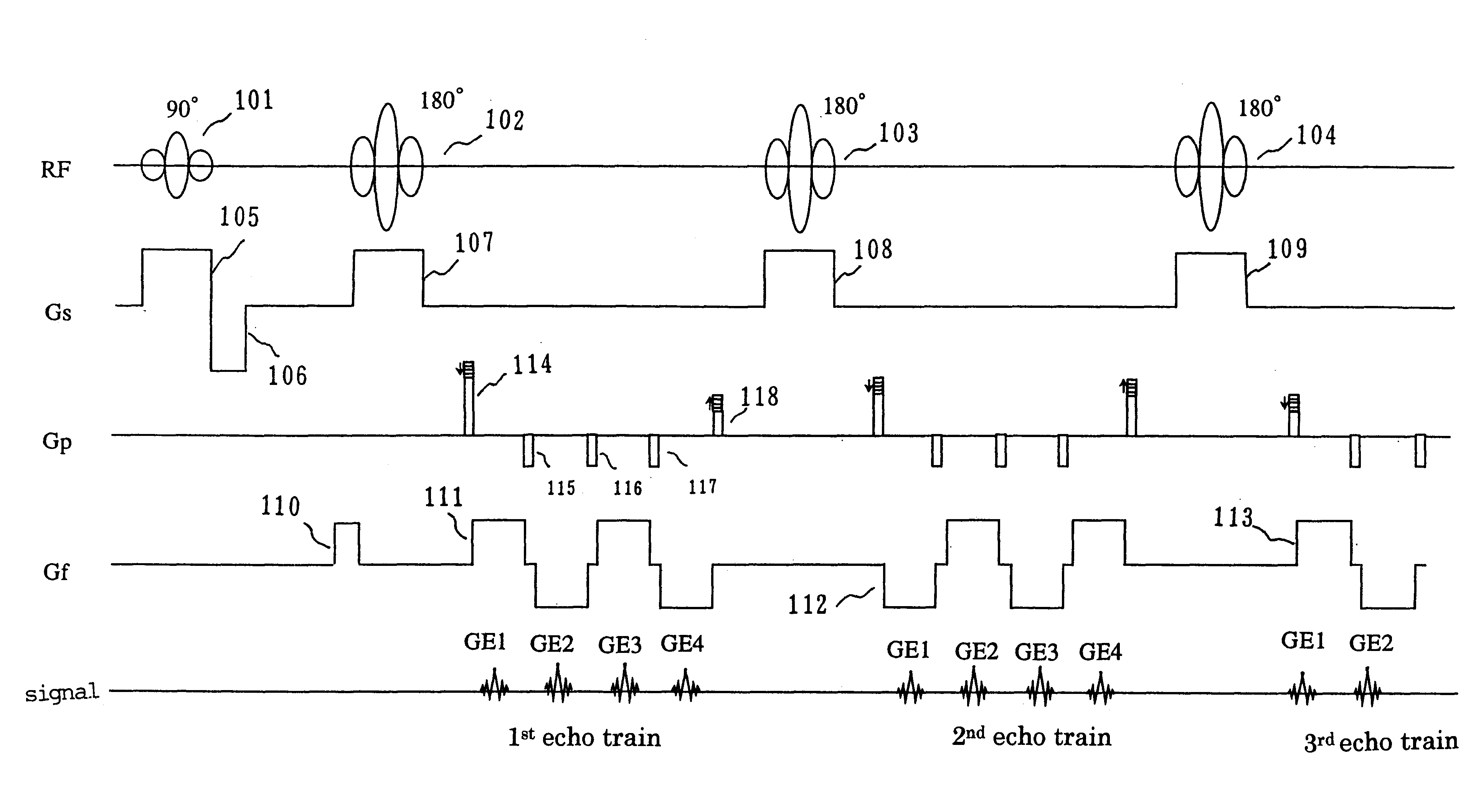
the present invention will be explained with reference to the timing chart shown in FIG. 5. This sequence is also based on the conventional hybrid sequence. Here, the timing of generation of the spin echo signal is different from the conventional sequence.

In this sequence, a 90.degree. pulse 101 is applied at first and then a plurality of 180.degree. pulses 102, 103 . . . are applied at constant intervals. As is in the embodiment of FIG. 1, the slice selective gradients Gs are applied together with the RF pulses. In this sequence, however, the interpulse time between two 180.degree. pulses is different from that in the sequence shown in FIG. 1. If the interval between the 90.degree. pulse and the first 180.degree. pulse is ETI.sub.1 / 2, the interpulse time between two 180.degree. pulses is longer than ETI.sub.1, i.e., ETI.sub.1 / 2+ETI.sub.2 / 2 (here, ETI.sub.2 >ETI.sub.1). In this condition, a spin echo signal SE is generated upon passage of time ETI.sub.1 / 2 after application of th...


PUM


Abstract

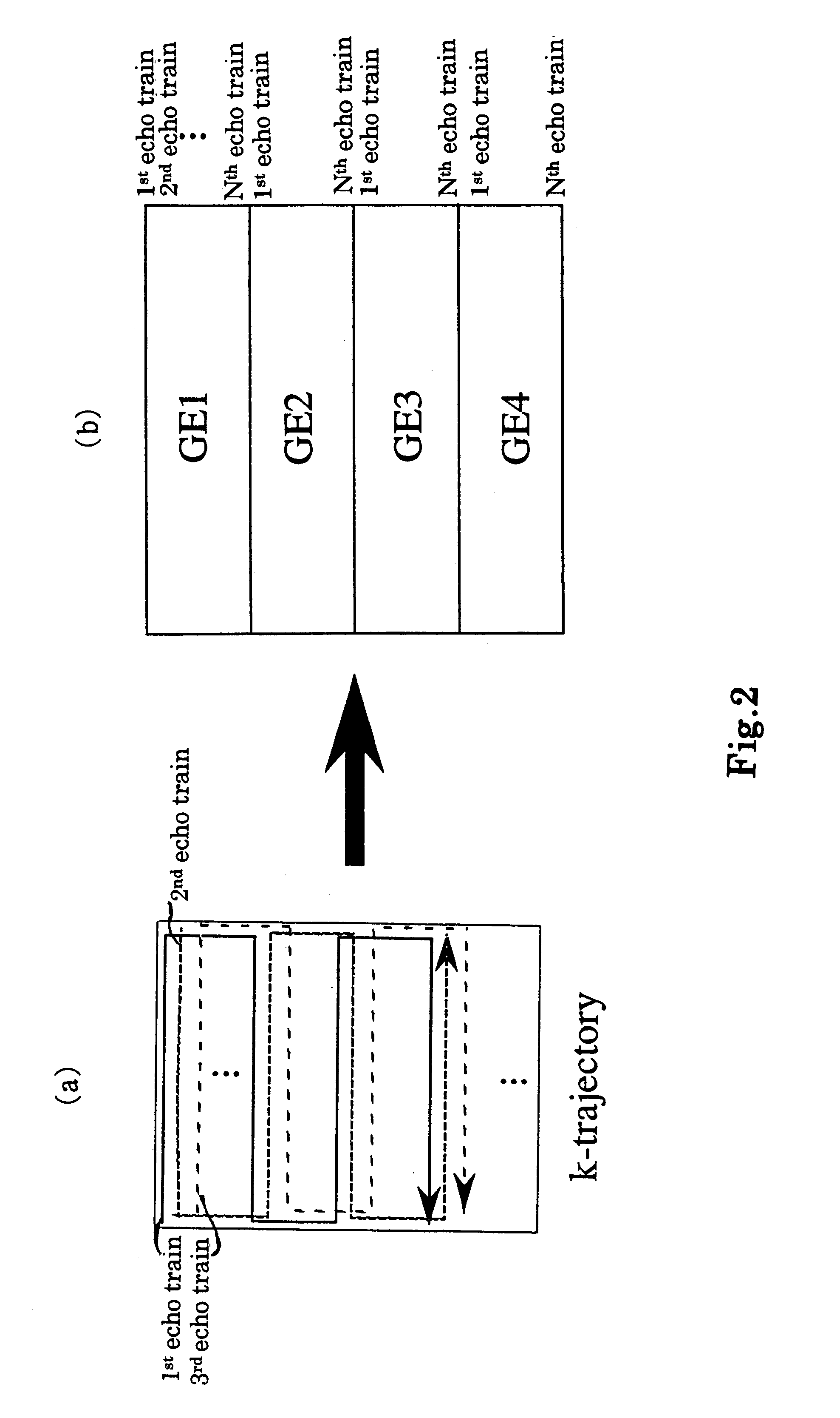
The MRI apparatus of the present invention performs a pulse sequence for applying successively 180° pulses 102, 103 . . . after application of a 90° pulse 101 at constant intervals and applying readout magnetic fields 111 during the interval between pairs of 180° pulses while the polarity of the magnetic field 111 is inverted several times to collect a plurality of gradient echo signals that are phase encoded differently. Here, the application of the readout gradient magnetic field is controlled such that generation of the gradient echo signals does ot coincide with generation of the spin echo signal. The image reconstruction is performed by using only T2* weighted gradient echo signals to obtain images reflecting difference in magnetic susceptibility and inhomogeneities in local magnetic fields.

Description

1. Field of the InventionThe present invention relates to a magnetic resonance imaging apparatus (abbreviated as "MRI apparatus" hereinafter) and an imaging method utilizing the MRI apparatus. In particular, it relates to an MRI apparatus and an imaging method capable of producing images with high sensitivity to difference in magnetic susceptibility and inhomogeneities in local magnetic fields.2. Related ArtKnown imaging methods utilizing MRI apparatuses include various kinds of sequences for fast imaging based on the spin echo imaging method or the gradient echo imaging method. Among such imaging methods, the fast spin echo method (FSE method) is an imaging method utilizing the multiple-echo method in which multiple echoes are generated by repeatedly applying 180.degree. pulses to inverse magnetization generated by excitation with 90.degree. pulses. The FSE method encompasses a method where each echo signal is differently phase-encoded to obtain one image fast, and a method in whic...

Claims


Application Information

Patent Timeline
Patent Type & Authority Patents(United States)
IPC IPC(8): G01R33/54G01R33/561G01R33/48A61B5/055
CPCG01R33/5615G01R33/5618
Inventor WATANABE, SHIGERUTAKAHASHI, TETSUHIKO
Owner HITACHI MEDICAL CORP
Why Eureka
Eureka Blog
Learn More