Automatic focusing apparatus

a focusing apparatus and automatic technology, applied in the direction of camera focusing arrangement, printers, instruments, etc., can solve the problems of comparatively high electric power, low shock resistance, complicated mechanism, etc., and achieve the effect of sufficient speed and precision

Inactive Publication Date: 2007-11-22
CITIZEN WATCH CO LTD
View PDF0 Cites 48 Cited by
  • Summary
  • Abstract
  • Description
  • Claims
  • Application Information

AI Technical Summary

Benefits of technology

[0020] To solve the problems in the conventional technology mentioned above, it is an object of the present invention to provide an automatic focusing apparatus that can detect the focus point with a sufficient speed and precision for practical use, by detecting a peak value of focus signals after collectively extracting plural focus signals corresponding to a focus matching degree during a transient response operation of a liquid crystal lens.
[0034] The automatic focusing apparatus according to the present invention, it is capable of detecting a focus point sufficiently speedily in practical use by using a liquid crystal lens for adjustment of focal length from the predetermined area set as area which extracts the focus signal of an entire image formation area, by collectively extracting a plurality of focus signals corresponding to focus matching degree during a transient response operation of the liquid crystal lens, and by detecting a maximum value (a peak value) of the focus signals.

Problems solved by technology

However, this system needs a lens drive mechanism and thus has defects that the mechanism becomes complicated and needs comparatively high electric power for the lens-drive motor.
Moreover, shock resistance is generally low.
However, adjustment of the focus by controlling changes in the refractive index of the liquid crystal lens by the hill-climbing control has not been reported, so far.
It is considered that is because the liquid crystal lens takes a long time to detect the focus point by the hill-climbing control.
However, since the response of the liquid crystal to the driving voltage change is generally delayed, it is necessary to wait after change of the driving voltage until the response of the liquid crystal is stabilized.
Therefore, the processing time per one position becomes long, for example 500 milliseconds, and the time to detect a focus point takes approximately 12.5 seconds (500 ms×25 positions) on average, and it is impractical.
Especially, when trying to pull out the power of the lens to the maximum extent, voltage difference between the core electrode and the peripheral electrode is made the maximum, thus on the side of the liquid crystal layer to which a lower voltage is applied, the lowest possible voltage at which liquid crystal molecules effectively operate is to be used, so that there has been a problem that a long time period is required until the lens becomes to have a suitable refractive index distribution on this side (until the transient response is completed).
However, when such a configuration is adopted, there has been a problem that the response of the liquid crystal becomes slow and a long time period is required until the lens becomes to have a suitable refractive index distribution.

Method used


Image

  • Automatic focusing apparatus
  • Automatic focusing apparatus
  • Automatic focusing apparatus

Examples


first embodiment

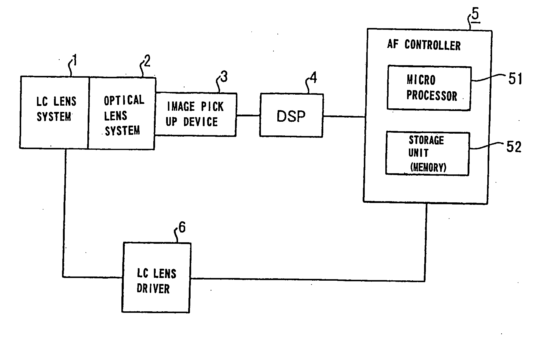
[0084] In this way, it takes a certain period of time for the liquid crystal to complete the transient response operation. Thus, in the first embodiment, the image signals generated from the optical images which have passed through the liquid crystal lens system 1 and the optical lens system 2 are sampled with a predetermined cycle during the transient response operation period of the liquid crystal. In FIG. 6, the processes of the changes in the refractive index of the liquid crystal and in the focal length of the liquid crystal lens 7 during the transient response operation period tf upon the rise of the driving voltage are shown.

[0085] For example, as shown in FIG. 6, the refractive index of the liquid crystal changes during the transient response operation period tf and becomes constant after the transient response operation period tf has passed, so that the refractive index of the part of the liquid crystal corresponding to the core electrode 20, to each of the ring electrodes ...

fourth embodiment

[0191] Here, control of the liquid crystal lens system 1 in the automatic focusing apparatus according to the embodiment is explained. Here, the change in the refractive index when voltage is applied to liquid crystal in a condition that the light with the polarization plane in the same direction as the alignment direction of the liquid crystal is passing through the liquid crystal is the same as that of the fourth embodiment shown in FIG. 25, therefore, explanation thereof is omitted. However, it is different from the embodiment on the point that the driving voltages V1, V2, and V3 in FIG. 25 are the pulse width modulated (PWM) alternating voltages, for example.

[0192] Next, the pulse width modulated (PWM) waveforms are shown in FIG. 30. The waveform corresponding to the driving voltage V1 with the smallest effective voltage is shown in upper side portion, the waveform corresponding to the driving voltage V2 with the largest effective voltage is shown in lower side portion, and the ...

second embodiment

[0204]FIG. 32 is a flowchart of the autofocus operation according to this embodiment, which is performed by the microprocessor 51 of the controller 5 in FIG. 1. In this flowchart and the flowchart in a second embodiment and the following explanation, “Step” is abbreviated to “S.”

[0205] The processing shown in FIG. 32 is started taking, as a trigger, the initial press of the shutter button of the image pickup apparatus such as a camera or the like incorporating this automatic focusing apparatus. The CMOS sensor corresponding to the image pickup device 3 shown in FIG. 1 is initialized first in S101 to set the number of frames and the number of pixels. Note that the setting of the number of frames and the number of pixels may be done in advance as an image pickup condition before the pressing of the button of the image pickup apparatus.

[0206] In the subsequent S102, the area from which the focus signal is extracted of an optical image formed passed through the optical lens unit includ...


PUM

PropertyMeasurementUnit
lengthaaaaaaaaaa
thicknessesaaaaaaaaaa
thicknessaaaaaaaaaa

Abstract

Predetermined voltage is applied to a liquid crystal lens by a liquid crystal lens driver. Image signals are generated based on an optical image passed through the liquid crystal lens during transient response operation caused by application of the predetermined voltage, and plural focus signals are extracted by sampling the image signals of the area from which the focus signals are extracted at predetermined cycles. Levels of the extracted focus signals are compared to determine the maximum value of the focus signal. Thus, with the liquid crystal lens, by making use of the transient response operation of the liquid crystal lens, a focus point can be detected in sufficient speed.

Description

BACKGROUND OF THE INVENTION [0001] 1. Field of the Invention [0002] The present invention relates to an automatic focusing apparatus (device), and particularly to an automatic focusing apparatus that detects a focus point using a liquid crystal lens for adjustment of focal length, by extracting plural focus signals corresponding to a focus matching degree from image signals obtained from optical images that are formed through the liquid crystal lens during transient response operation of the liquid crystal lens, and by detecting a maximal value of the focus signal. [0003] 2. Description of the Related Art [0004] Conventionally, as a focus mechanism changing the focal length or focus position of an optical system, the system of adjusting the focus by moving a lens has been widely used. However, this system needs a lens drive mechanism and thus has defects that the mechanism becomes complicated and needs comparatively high electric power for the lens-drive motor. Moreover, shock resis...

Claims


Application Information

Patent Timeline
Patent Type & Authority Applications(United States)
IPC IPC(8): G02F1/1335
CPCG02F1/1313G02F1/134309G02F1/29H04N5/23212G02F2203/28G03B3/00H04N5/2254G02F2001/294G02F1/294H04N23/675
Inventor KATO, YUICHIKAWADA, TAKAHIRO
Owner CITIZEN WATCH CO LTD
Why Eureka
Try Eureka