Supercharge Your Innovation With Domain-Expert AI Agents!

Projection device with solar cell panel

a solar cell and projection device technology, applied in the direction of projectors, instruments, optics, etc., can solve the problems of device cooling, light sheltering, energy utilization, and the inability to solve the problem of the original design, and reduce the expected efficiency owing to the original design. , to achieve the effect of extending the life of the projection device and promoting cooling efficiency in the housing

Inactive Publication Date: 2007-11-22
DELTA ELECTRONICS INC
View PDF19 Cites 2 Cited by
  • Summary
  • Abstract
  • Description
  • Claims
  • Application Information

AI Technical Summary

Benefits of technology

The invention is a projection device that uses a solar cell panel to convert light from a light source into electric power. The device also has an airflow channel between the solar cell panel and the light source or other components to improve cooling efficiency and extend the life of the device. The solar cell panel not only shelters light leakages but also effectively uses energy resources. The invention reduces the complexity of components, simplifies the mold design, and decreases costs. The technical effects of the invention include improved cooling efficiency, increased lifespan, and reduced complexity and costs.

Problems solved by technology

However, the above-mentioned improvements would add further complexities in the manufacturing processes, materials, and assembling procedures.
Furthermore, the problems of light sheltering, energy utilizing, and device cooling could not be simultaneously resolved.
If the aforementioned method of resolving individual problems is not considered in advance, the invention may affect other aspects, and therefore, probably reduce the expected efficiency owing to the original design.
The interference of the dragging airflows is disadvantageous in forming a preferred virtual airflow channel for the airflows 12 to travel along, thereby, reducing the cooling efficiency.
Nevertheless, the cooling problems still need to be solved independently.
Accordingly, this increases not only the interior components, but also the complexities of the molds and manufacturing costs.

Method used


Image

  • Projection device with solar cell panel
  • Projection device with solar cell panel
  • Projection device with solar cell panel

Examples


Embodiment Construction

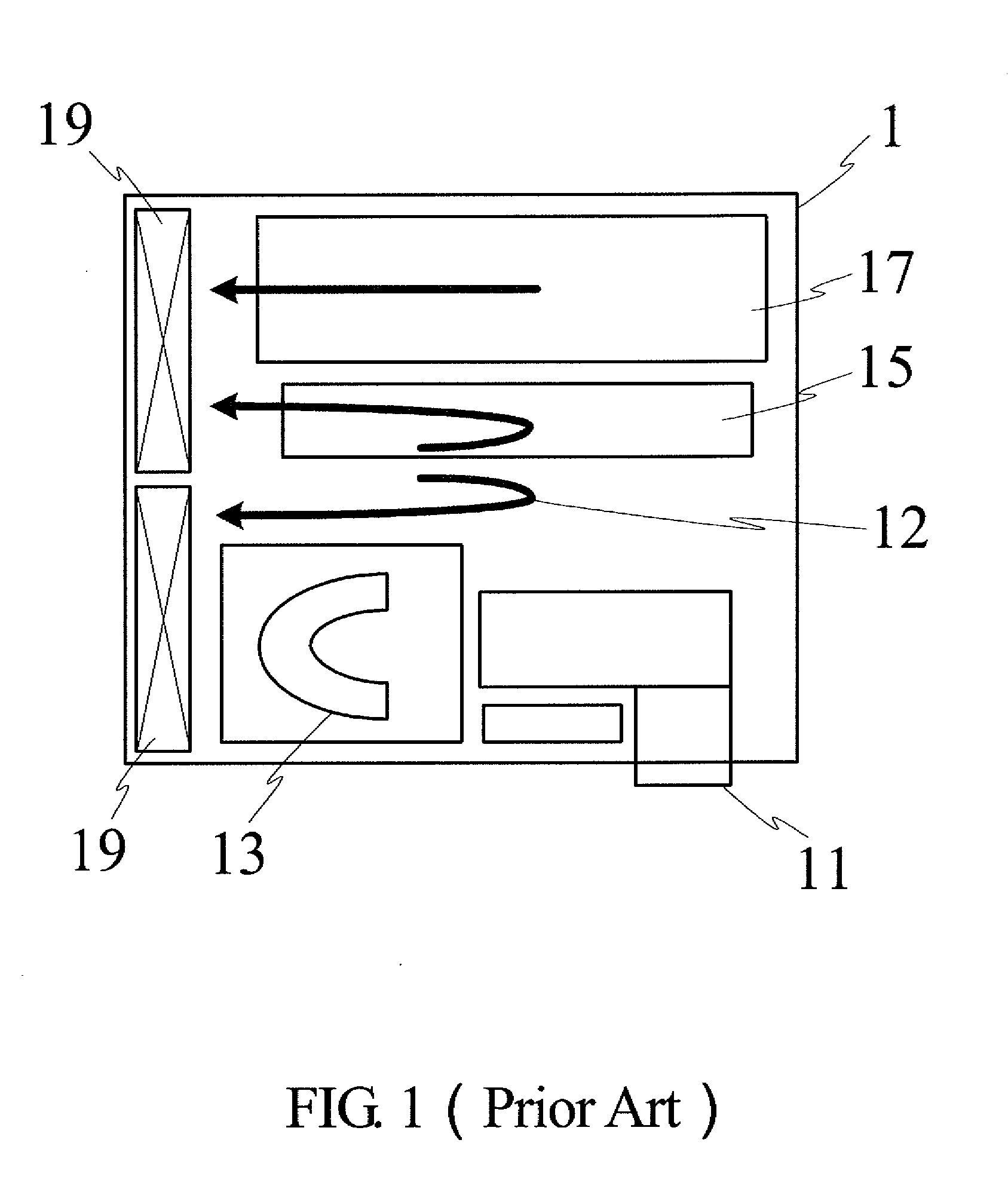
[0020]The projection device 2 illustrated in the figures of the present invention is arranged three-dimensionally in reality. The so-called “airflow channels” are virtually defined without physical contours. They may refer to irregular three-dimension passage(s). Therefore, the designated numerals in the drawings may not be precisely indicated to the right places. The “cooling airflows” guided within the airflow channels, which are difficult to represent, are denoted by representative arrows.

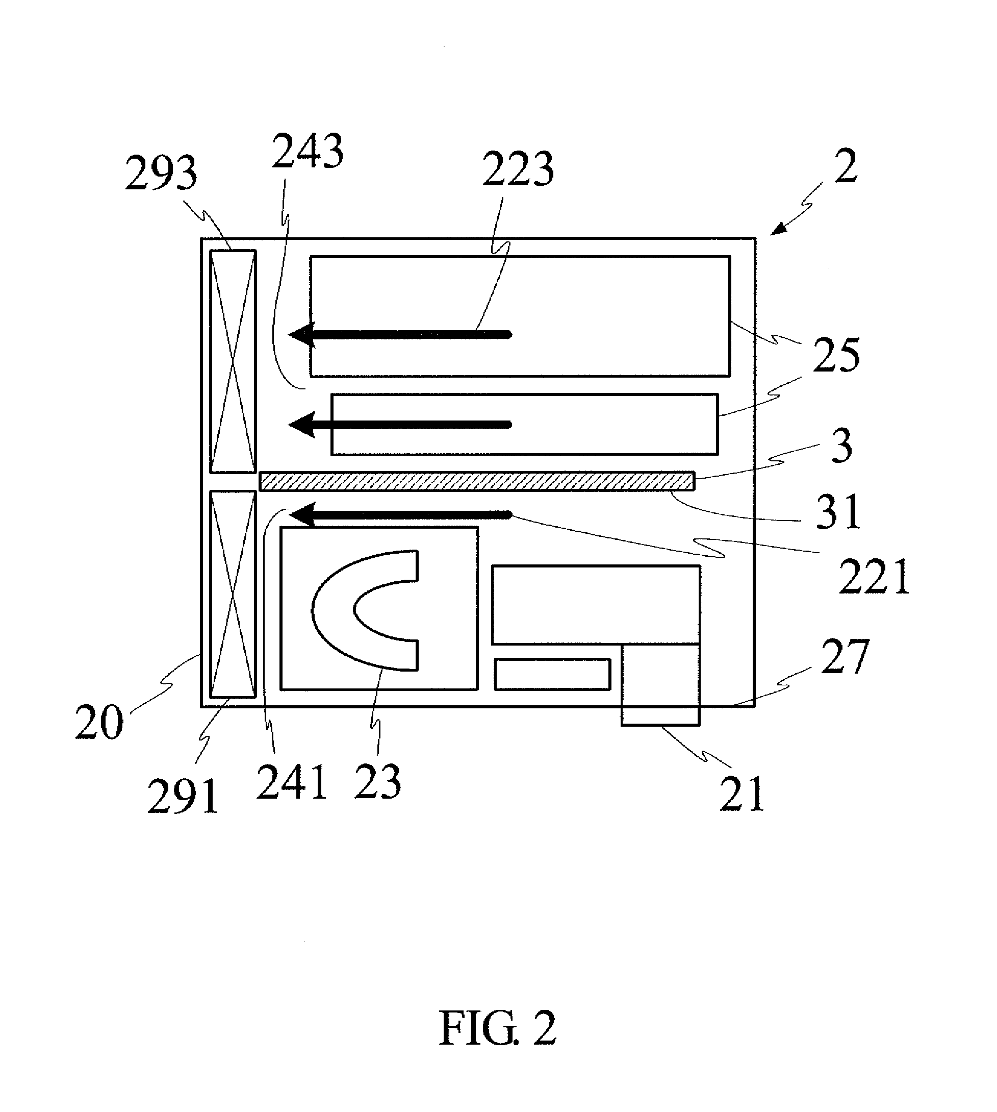
[0021]FIG. 2 is a schematic view illustrating a preferred embodiment of the present invention. The projection device 2 comprises an end portion 20, a light source 23, a solar cell panel 3, and a first fan 291. Preferably, the light source 23 is a bulb, which is utilized to provide sufficient light for an optical engine 21. The solar cell panel 3 has a light receiving surface 31 facing the light source 23 for converting a portion of light, which is projected from the light source 23 or the light ...


PUM


Abstract

The present invention relates to a projection device which comprises a light source, a solar cell panel, an airflow channel, and a fan. The airflow channel is formed between the solar cell panel and the light source, while the fan is utilized to generate airflow along the airflow channel. The airflow channel can be alternatively formed between the solar cell panel and other components of the projection device. With this arrangement, the solar cell panel can convert the unused light into electric power, while simultaneously forming an airflow channel for cooling the device.

Description

[0001]This application benefits from the priority of Taiwan Patent Application No. 095117251 filed on May 16, 2006.CROSS-REFERENCES TO RELATED APPLICATIONS[0002]Not applicable.BACKGROUND OF THE INVENTION[0003]1. Field of the Invention[0004]The present invention relates to a projection device. In particular, the invention relates to a projection device that has an airflow channel, formed by a solar cell panel, to aid in cooling the interior of the device.[0005]2. Descriptions of the Related Art[0006]Because energy resources are limited, it is important to consider energy conservation and environmental protection while developing technology. In the area of luminescence technologies for projectors, not only should the efficiency of the light source be considered, but other factors should also be considered to enhance the entire quality of the projectors. For example, the internal light that shines from the projector needs to be covered to keep users from being irritated. In addition, a...

Claims


Application Information

Patent Timeline
Patent Type & Authority Applications(United States)
IPC IPC(8): G03B21/16
CPCG03B21/16
Inventor CHANG, HSIU-MING
Owner DELTA ELECTRONICS INC
Features
  • R&D
  • Intellectual Property
  • Life Sciences
  • Materials
  • Tech Scout
  • Unparalleled Data Quality
  • Higher Quality Content
  • 60% Fewer Hallucinations
Learn More