Head floating amount control method and unit, storage apparatus and computer-readable program

a floating amount and control method technology, applied in the direction of maintaining head carrier alignment, recording information storage, instruments, etc., can solve the problems of head crash, deterioration of electromagnetic conversion characteristic efficiency, and possibility of generating, to a certain exten

Active Publication Date: 2007-11-22
KK TOSHIBA
View PDF4 Cites 12 Cited by
  • Summary
  • Abstract
  • Description
  • Claims
  • Application Information

AI Technical Summary

Benefits of technology

[0016]Another and more specific object of the present invention is to provide a head floating amount control method, a head floating amount control unit, a storage apparatus and a computer-readable storage medium, which can control the floating amount of the individual head with respect to the recording media to an optimum value.
[0017]Still another object of the present invention is to provide a head floating amount control unit for controlling a head floating amount of each of a plurality of heads respectively having a heater, with respect to a recording medium, comprising a detecting part configured to detect contact between each head and a corresponding recording medium by detecting a thermal asperity or a read error, and to judge a heating amount of the heater at a time when the contact is detected as a state where the head floating amount is zero; and a control part configured to control the head floating amount of each head to an optimum head floating amount based on a relationship of the heating amount of the heater and an amount of thermal expansion of each head. According to the head floating amount control unit of the present invention, it is possible to control the floating amount of the individual head with respect to the recording medium to an optimum value.
[0018]A further object of the present invention is to provide a storage apparatus comprising a plurality of heads respectively having a heater; a contact detecting part configured to detect a contact between each head and a corresponding recording medium by detecting a thermal asperity or a read error; and a control part configured to control a head floating amount of each head to an optimum head floating amount based on a relationship of a heating amount of the heater and an amount of thermal expansion of each head, regarding the heating amount of the heater at a time when the contact is detected as a state where the head floating amount is zero. According to the storage apparatus of the present invention

Problems solved by technology

For this reason, in a case where the inconsistency is large and particularly when the floating amount is small, the margin of the HDI with respect to the magnetic spacing deteriorates to thereby generate the possibility of the head crash.
On the other hand, when the floating amount is large, the efficiency of the electromagnetic conversion characteristic deteriorates due to the increase of the magnetic spacing.
Consequently, there was a possibility of generating, to a certain extent, deterioration in the reproduced output, generation of the read error, and generation of the seek operation error caused by the read error with respect to the servo signal.
Furthermore, when the floating amount is small, there was a possibility of the head colliding with the projections on the surface of the magnetic disk.
As a result, there was a possibility of generating the read error due to the thermal asperity or, causing damage to both the head and the magnetic head due to the head colliding with the magnetic disk surface because of the repeated generation of the thermal asperity.
In this case, the head crash may occur due to the change in the floating amount or the floating position of the head due to the damage caused by the contact between the head and the magnetic disk.
Therefore, conventionally, particularly when the inconsistency among the floating amounts of the individual heads is large, the margin with respect to the magnetic spacing of the HDI deteriorates if the floating amount is small, and there was a possibility of generating the head crash.
In addition, if the floating amount is

Method used


Image

  • Head floating amount control method and unit, storage apparatus and computer-readable program
  • Head floating amount control method and unit, storage apparatus and computer-readable program
  • Head floating amount control method and unit, storage apparatus and computer-readable program

Examples


Embodiment Construction

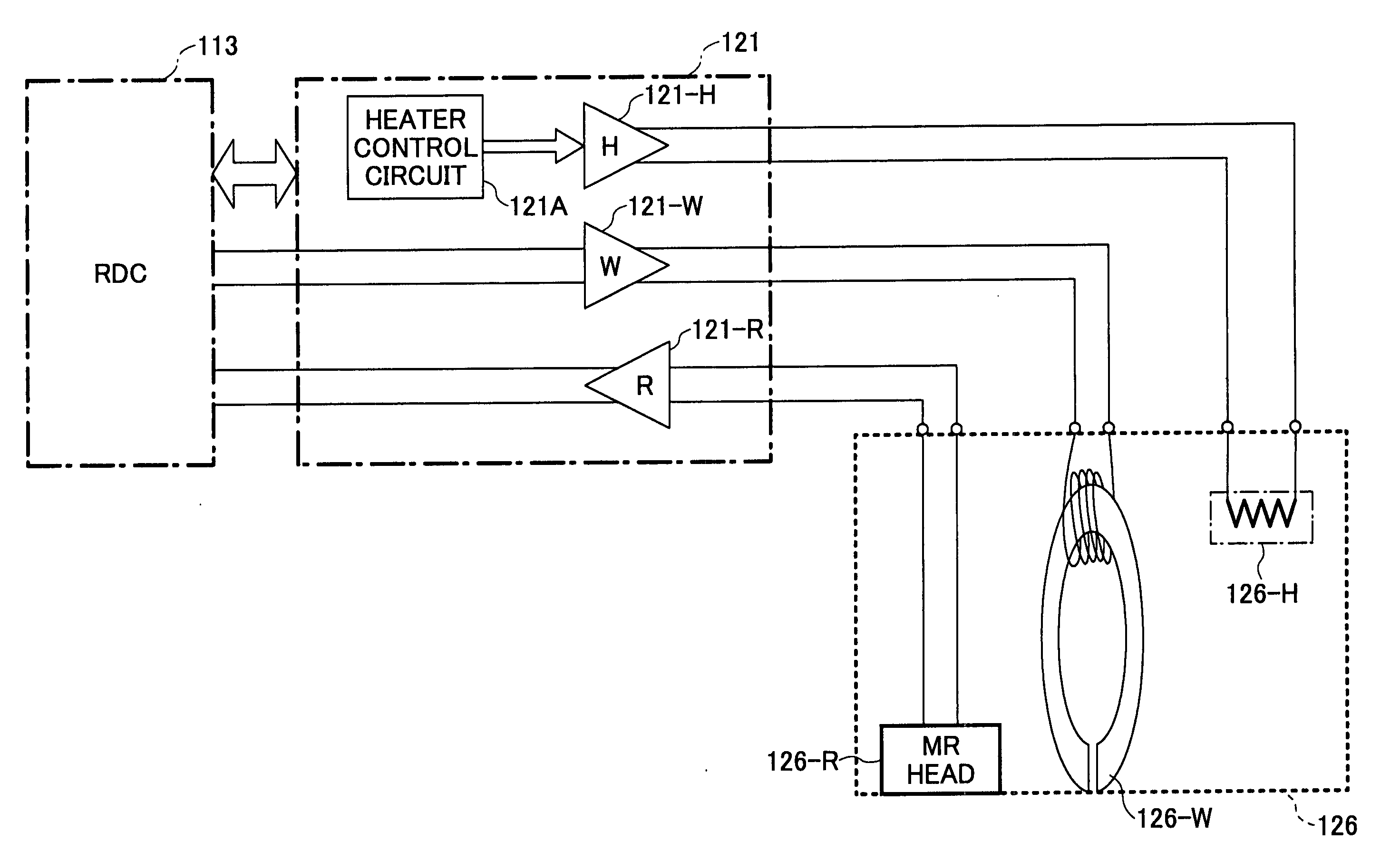
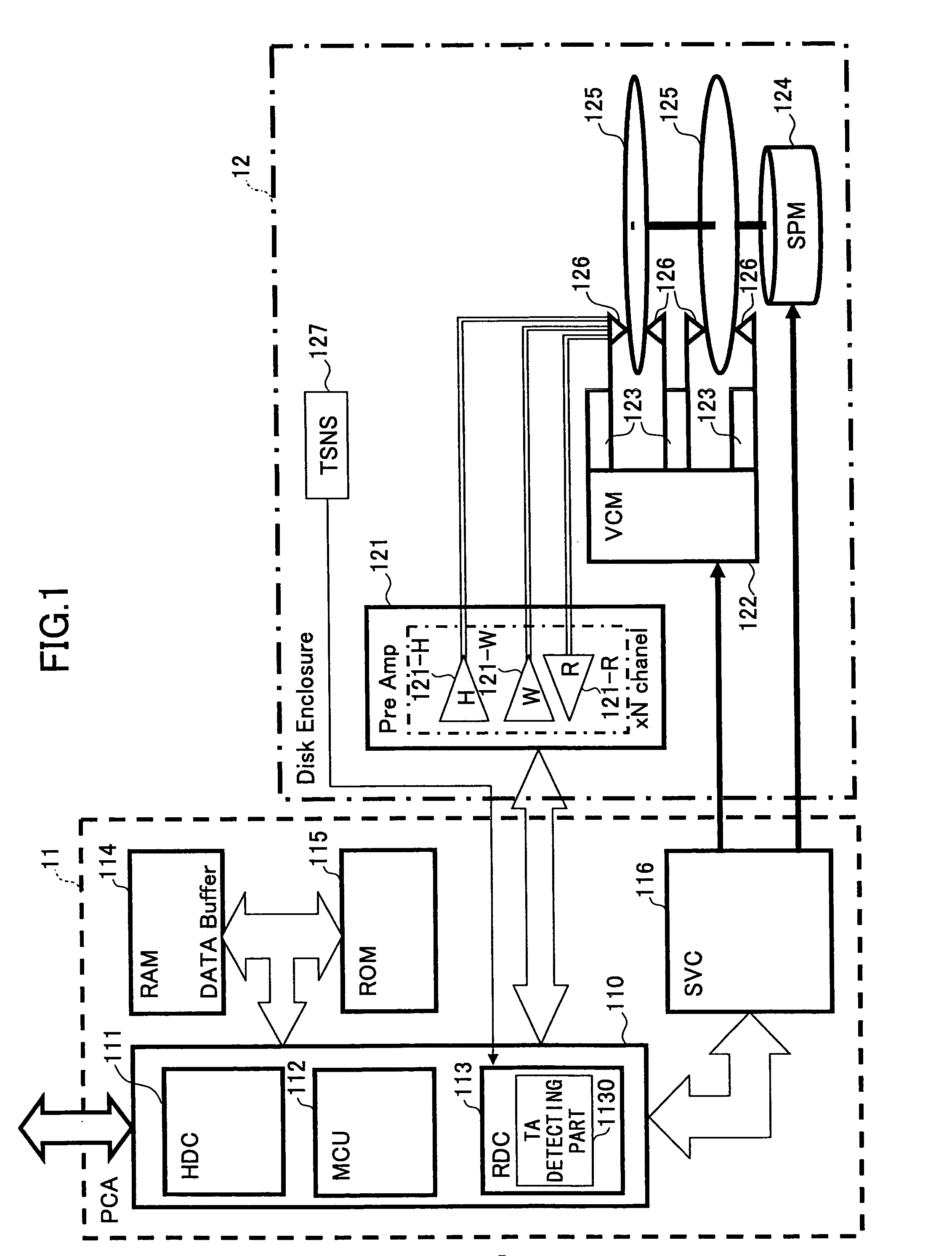
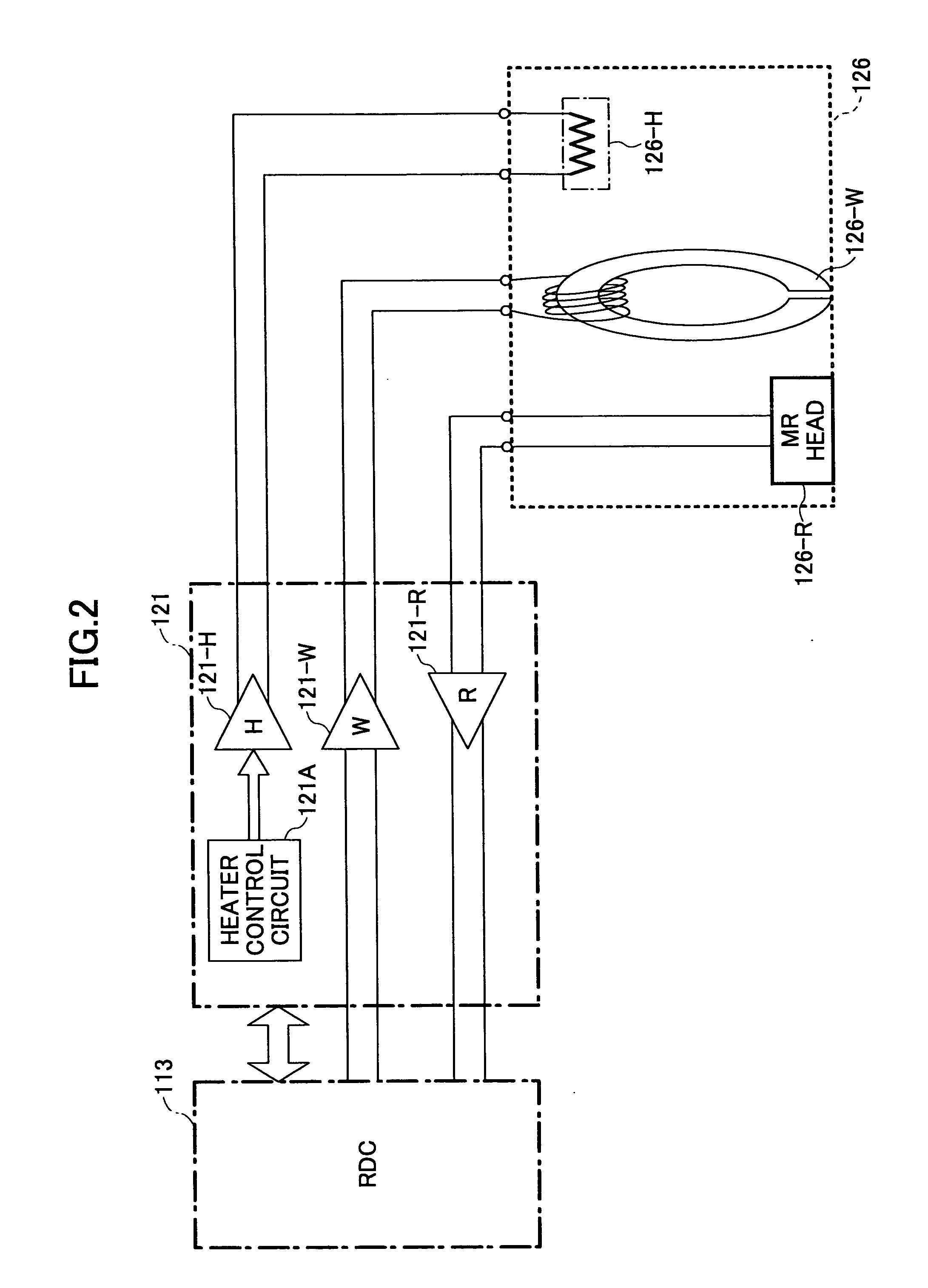
[0040]According to the present invention, in a storage apparatus having a head provided with a heater for heating in a vicinity of a head element, the head is thermally expanded by the heating provided by the heater, and a floating amount of the head element with respect to a recording medium is gradually reduced. In a case where the head element and the recording medium make contact with each other, a thermal transient response is generated in a read signal that is output from the head due to the collision thermal energy at the time of the contact. Generally, this phenomenon is referred to as a thermal asperity. Hence, the contact between the head element and the recording medium is detected by detecting this thermal asperity, and a heating amount of the heater at the time when the thermal asperity is detected is judged as being a state where the floating amount of the head element with respect to the recording medium. Thereafter, the floating amount of each of the individual heads...


PUM


Abstract

A head floating amount control unit control a head floating amount of each of a plurality of heads respectively having a heater, with respect to a recording medium, by detecting contact between each head and a corresponding recording medium by detecting a thermal asperity or a read error, and judging a heating amount of the heater at a time when the contact is detected as a state where the head floating amount is zero, and controlling the head floating amount of each head to an optimum head floating amount based on a relationship of the heating amount of the heater and an amount of thermal expansion of each head.

Description

BACKGROUND OF THE INVENTION[0001]1. Field of the Invention[0002]The present invention generally relates to head floating amount control methods and units, storage apparatuses and computer-readable programs, and more particularly to a head floating amount control method and a head floating amount control unit for controlling a floating amount of a head with respect to a recording medium, a storage apparatus which uses such a head floating amount control unit, and a computer-readable program which causes a computer to control the floating amount of the head by such a head floating amount control method. The present invention also related to a computer-readable storage medium which stores such a computer-readable program.[0003]2. Description of the Related Art[0004]Storage apparatuses such as hard disk drives (HDDs) are used in various apparatuses such as desk-top personal computers, lap-top personal computers, servers, audio visual (AV) equipments, various kinds of portable electronic...

Claims


Application Information

Patent Timeline
IPC IPC(8): G11B21/02
CPCG11B5/607G11B5/6005G11B5/60G11B21/21
Inventor TAKAHASHI, TSUYOSHI
Owner KK TOSHIBA
Why Eureka
Try Eureka