
Portable X-Ray Device

Active Publication Date: 2007-11-22
ARIBEX
View PDF46 Cites 43 Cited by
  • Summary
  • Abstract
  • Description
  • Claims
  • Application Information

AI Technical Summary

Benefits of technology

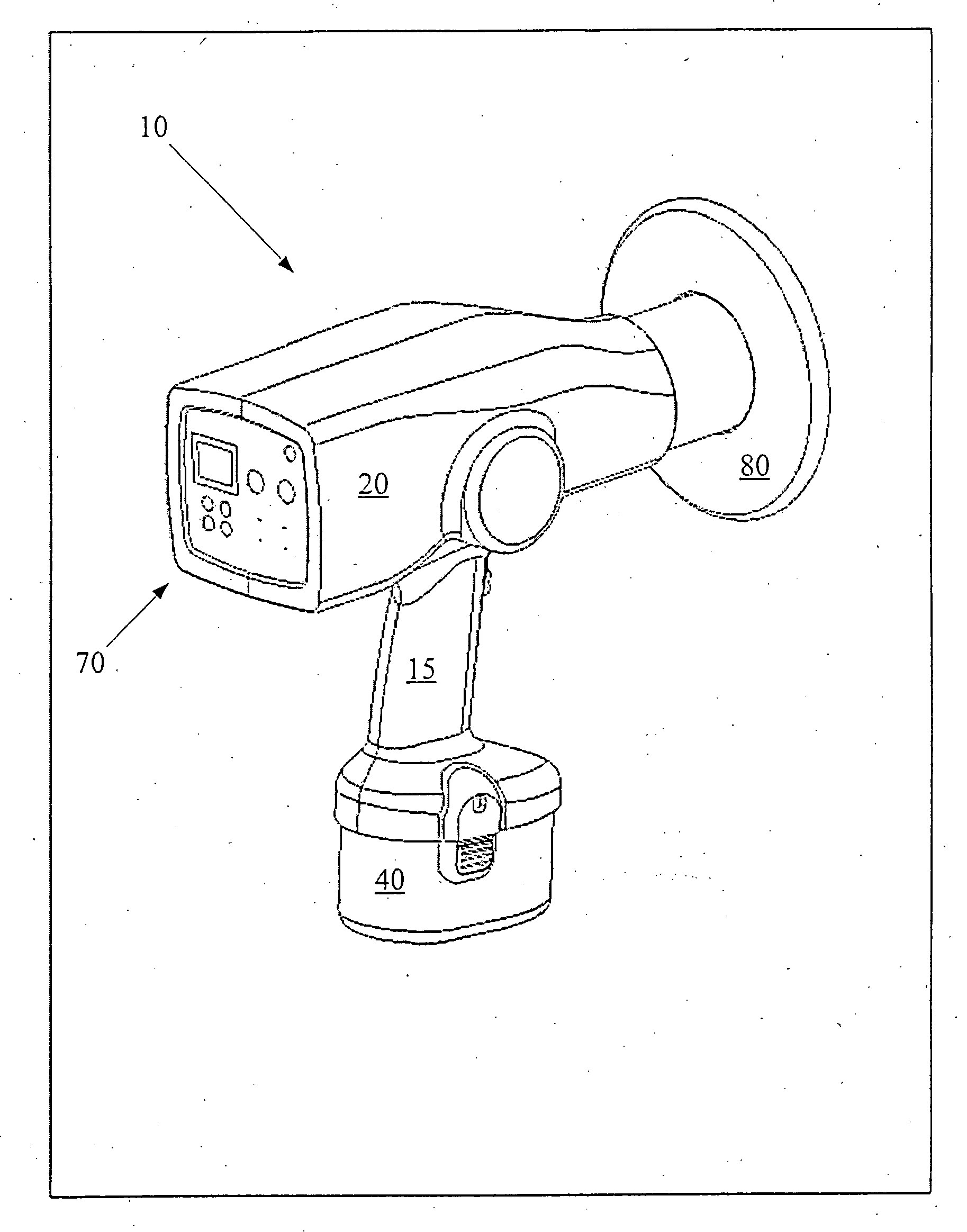
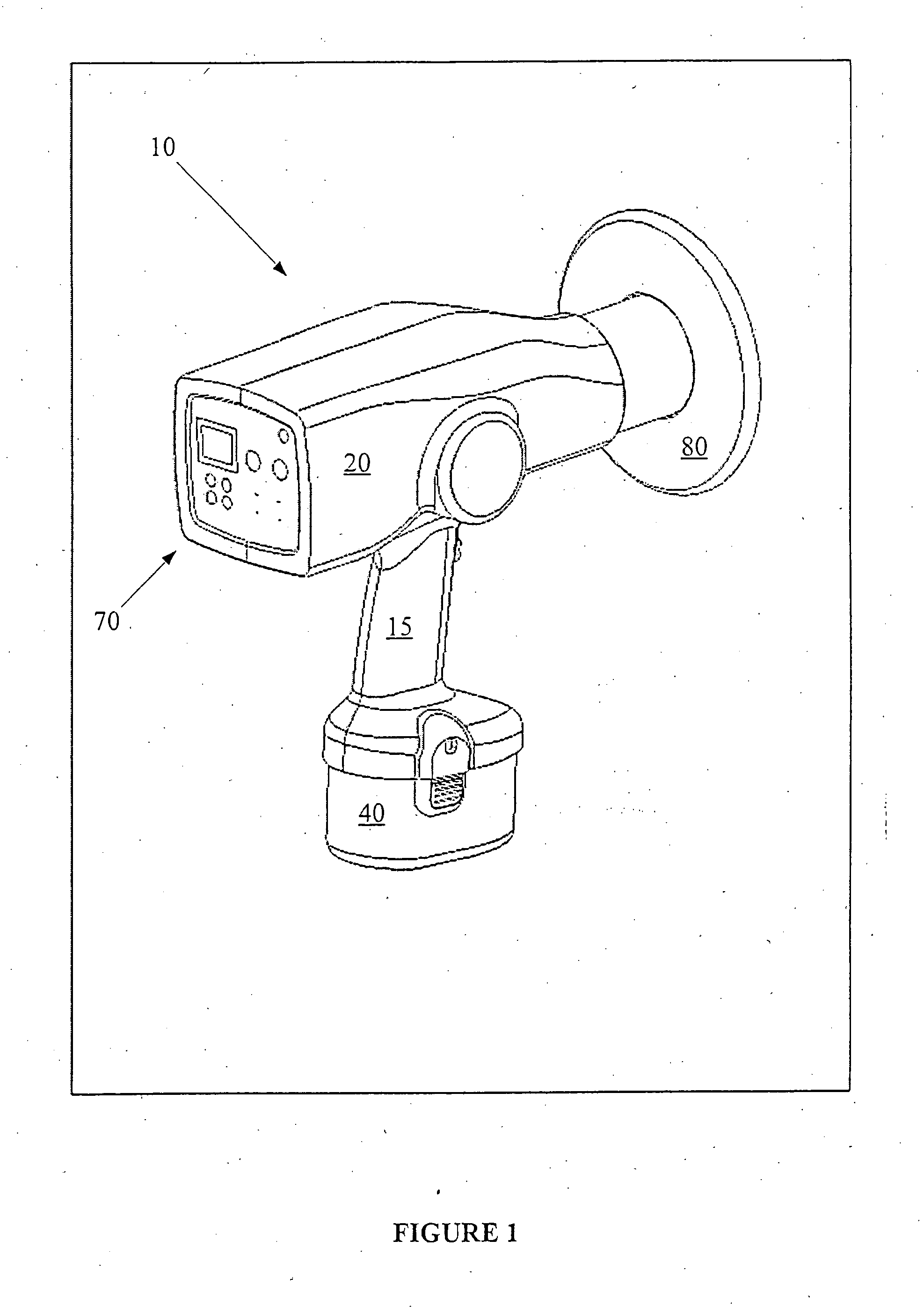
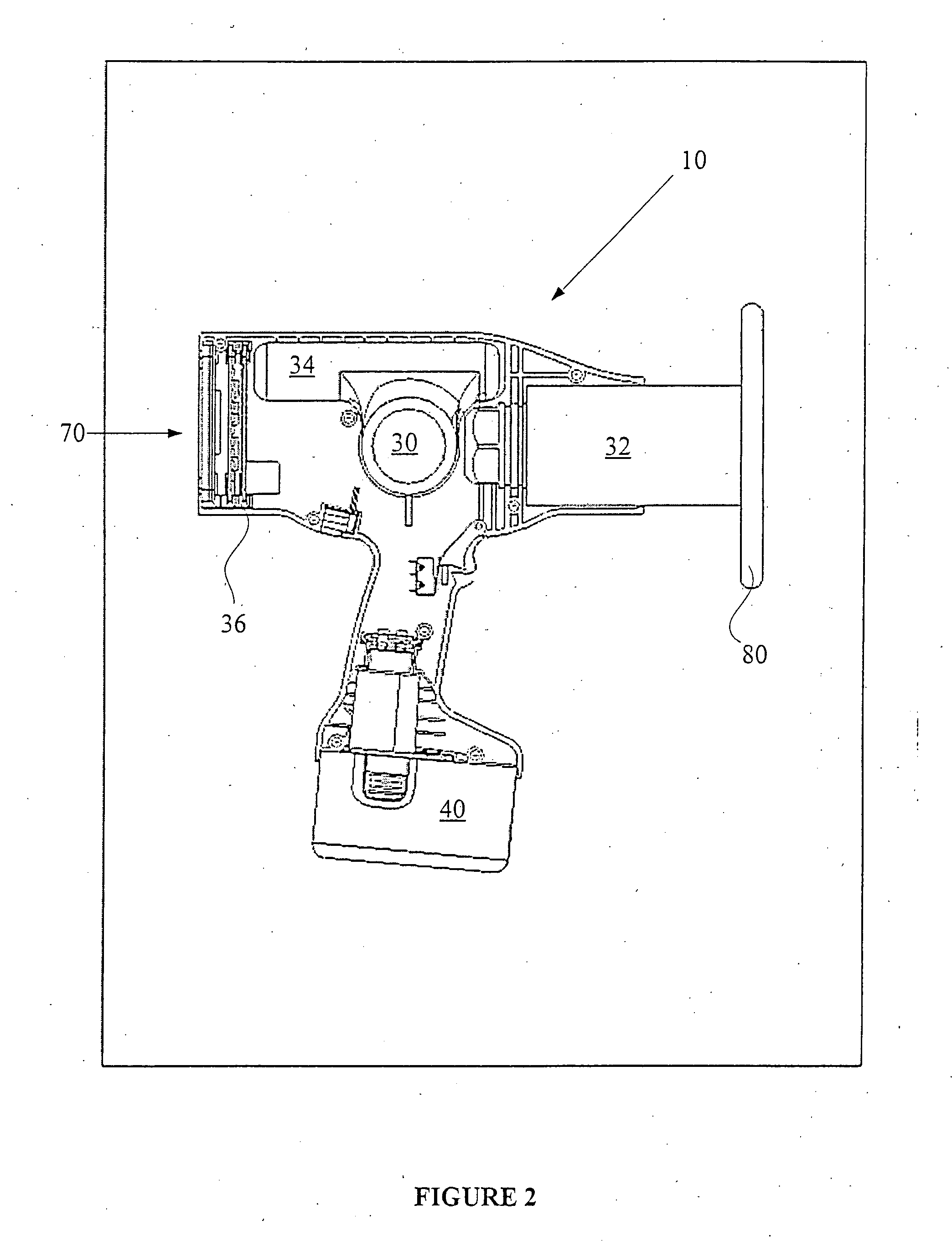
[0007] The invention relates to portable x-ray devices and methods for using such devices. The devices have an x-ray tube powered by an integrated power system. The x-ray tube is shielded with a low-density insulating material containing a high-Z substance. The devices can also have an integrated display component. With these components, the size and weight of the x-ray devices can be reduced, and the portability of the devices enhanced. Thus, the portable x-ray devices are especially useful for applications where portability is an important feature such as in field work, remote operations, and mobile operations such nursing homes, home healthcare, teaching classrooms. This portability feature can be particularly useful in multi-suite medical and dental offices where a single x-ray device can be used in multiple offices instead of single using an x-ray device in each office.

Problems solved by technology

Unfortunately, they are usually bulky and are powered by heavy, high-voltage power supplies that restrict mobility.
As well, they are often difficult and time-consuming to use.
These limitations can be very inconvenient for many popular uses of x-ray devices containing them.
At the same time, however, these designs are limited for several reasons.
First, most of the designs are not truly portable since they have an external power source (i.e., require utility-supplied line voltage).
Second, while some of the portable designs, especially the XRF systems, have internal or “integrated” power supplies, they don't have the high x-ray tube current load that is often necessary for x-ray imaging.
Finally, the radiation shielding for the x-ray tubes usually comprises lead, which is quite heavy and limits the portability of the device.
A further limitation on design of the increased portability is the image collection and display components.
Such a configuration, however, increases the size of the device and the number of system components, and consequently decreases the portability of the device.

Method used


Image

  • Portable X-Ray Device
  • Portable X-Ray Device
  • Portable X-Ray Device

Examples


Embodiment Construction

[0017] The following description provides specific details in order to provide a thorough understanding of the invention. The skilled artisan, however, would understand that the invention can be practiced without employing these specific details. Indeed, the invention can be practiced by modifying the illustrated method and resulting product and can be used in conjunction with apparatus and techniques conventionally used in the industry. While the invention is described for use in x-ray imaging for dental purposes, it could be used in other medical applications such as medical imaging, veterinary, and bone densitometry. As well, it could be used for non-dental and non-medical applications such as industrial imaging, metal fatigue inspections, weld-inspection for cracks / voids and pipes, for security inspections allowing random inspection of parcels and carry-on baggage, and the like.

[0018] As described above, the invention includes a portable x-ray device that is used primarily for ...


PUM


Abstract

Portable x-ray devices and methods for using such devices are described. The devices have an x-ray tube powered by an integrated power system. The x-ray tube is shielded with a low-density insulating material containing a high-Z substance. The devices can also have an integrated display component. With these components, the size and weight of the x-ray devices can be reduced, and the portability of the devices enhanced. Thus, the portable x-ray devices are especially useful for applications where portability is an important feature such as in field work, remote operations, and mobile operations such nursing homes, home healthcare, teaching classrooms. This portability feature can be particularly useful in multi-suite medical and dental offices where a single x-ray device can be used in multiple offices instead of single using an x-ray device in each office.

Description

CROSS-REFERENCE TO RELATED APPLICATION [0001] This application claims priority of U.S. Patent Application Ser. No. 60 / 546,575, filed on Feb. 20, 2004, the entire disclosure of which is incorporated herein by reference.FIELD OF THE INVENTION [0002] The invention generally relates to x-ray devices and methods for using the same. More particularly, the invention relates to x-ray tubes used in x-rays devices. Even more particularly, the invention relates to portable x-ray devices that contain an integrated power system, methods for using such portable x-ray devices, and systems containing such portable x-ray devices. BACKGROUND OF THE INVENTION [0003] Typical x-ray tubes and x-ray devices (device containing x-ray tubes) have been known and used for some time. Unfortunately, they are usually bulky and are powered by heavy, high-voltage power supplies that restrict mobility. As well, they are often difficult and time-consuming to use. In many instances, a sample for analysis must be sent ...

Claims


Application Information

Patent Timeline
IPC IPC(8): H05G1/10A61B6/00H05G1/06
CPCA61B6/4405H05G1/06A61B6/508H05G1/10A61B6/548H05G1/08H05G1/00
Inventor TURNER, D. CLARK
Owner ARIBEX
Learn More