Hydraulic elevation apparatus and method

a technology of hydraulic equipment and hydraulic lift, which is applied in the direction of earth-moving drilling and mining, loading/unloading, bulk conveyors, etc., can solve the problems of inefficient and relatively costly methods and devices used to lift rocks, insufficient space utilization, and insufficient efficiency of hoisting materials individually or by load in existing vertical shafts. , to achieve the effect of reducing the number of cylinders, and reducing the number of cylinder

Inactive Publication Date: 2007-11-22
GUENTHER ROSS
View PDF10 Cites 7 Cited by
  • Summary
  • Abstract
  • Description
  • Claims
  • Application Information

AI Technical Summary

Benefits of technology

[0051]Viewed from a twenty-fourth vantage point, it is an object of the present invention to provide a method for transporting animate or inanimate objects employing flotation elevation, comprising (A) depositing a transport container into a first chamber of a multiple chamber framework internally disposed within at least one single shaft structure; (B) loading or unloading said tra

Problems solved by technology

A persistent and formidable challenge in mining and related industries is implementing cost effective, efficient and reliable devices and methods for lifting objects either from beneath the earth's surface or to elevations above the earth's surface.
For instance, currently within the underground mining industry, demonstrably inefficient and relatively costly methods and devices are employed to lift rock and other objects from subsurface levels to above the earth's surface.
However, hoisting materials either individually or by load in existing vertical shafts is often inordinately space consuming, time consuming, costly, and consequently inefficient.
Vertical shaft hoisting generally requires an entire shaft compartment to lift a single load contained in a bucket or similar container, and additionally requires considerable time to lower the container back down the same shaft compartment to complete the hoisting cycle of a single container.
Moreover, vertical shaft hoist lifting devices and methods require the use of relatively expensive equipment, including hoists, wire rope, and corresponding mechanical parts, which are not only high maintenance, but also demand frequent replacement as a consequenc

Method used


Image

  • Hydraulic elevation apparatus and method
  • Hydraulic elevation apparatus and method
  • Hydraulic elevation apparatus and method

Examples


first embodiment

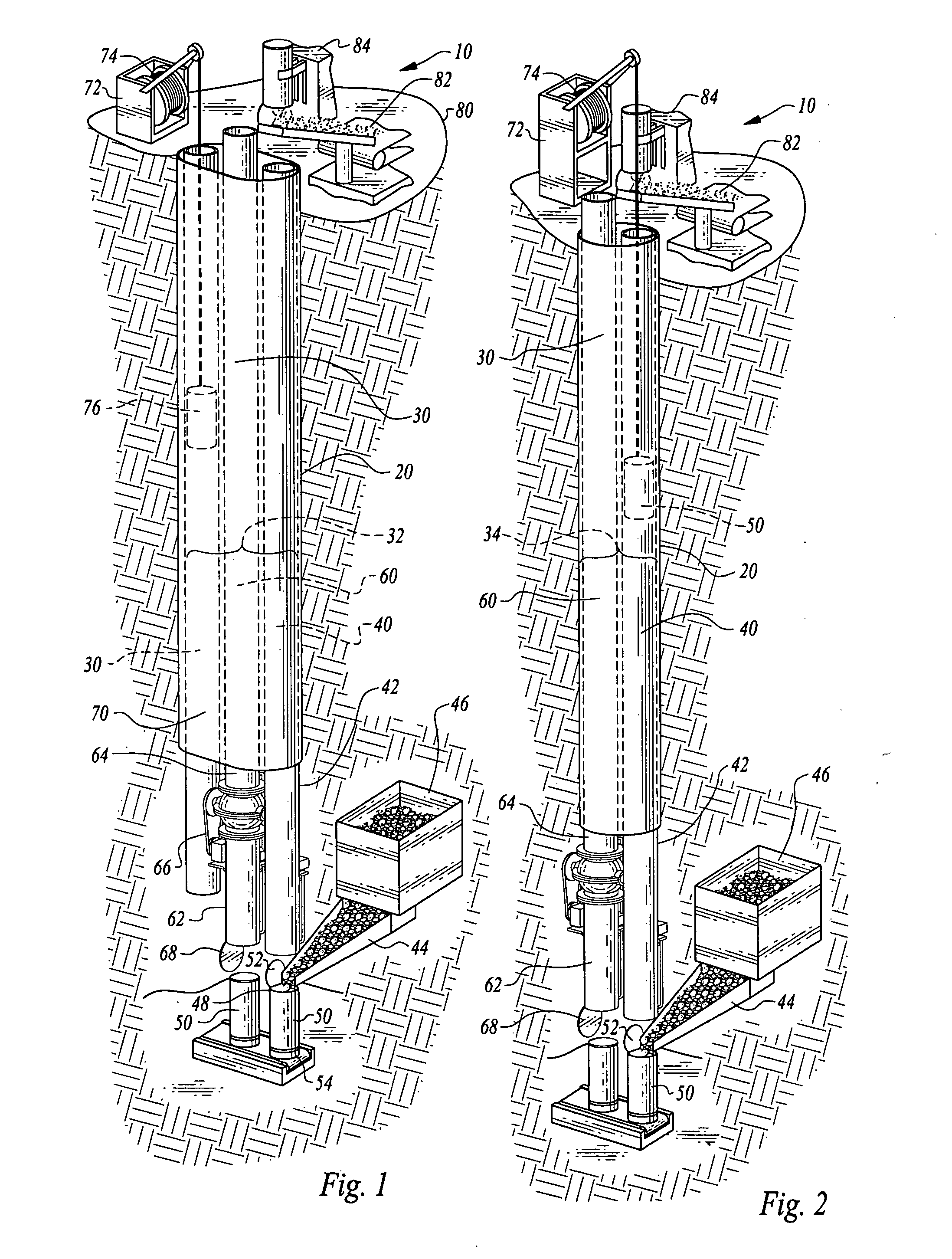
[0079]FIGS. 1 and 2 depict preferred embodiments of elevation apparatus (10) in a vertical lifting orientation. FIG. 1 shows elevation apparatus (10) employing a chamber framework (30) comprising a tripartite cavity structure (32) positioned within shaft elevation structure (20). Tripartite cavity structure (32) of chamber framework (30) includes a return chamber (40), a transport container (50), a delivery chamber (60), and an auxiliary hoist chamber (70). Auxiliary hoist chamber (70) may be optionally positioned laterally and adjacent to delivery chamber (60). A surface hoist (72) comprising a pulley mechanism (74) and an operatively attached transport container (76) is employed within auxiliary hoist chamber (70) as an optional lifting mechanism to transport objects within chamber framework (30).

second embodiment

[0080]FIG. 2 shows the elevation apparatus (10) employing a chamber framework (30) comprising a dual cavity structure (34) positioned within shaft elevation structure (20). Dual cavity structure (34) of chamber framework (30) includes a return chamber (40), a transport container (50), and a delivery chamber (60). As depicted in FIG. 2, transport container (50) may be lowered within return chamber (40) via a hoist, pulley, or similar such mechanism. Return chamber (40) includes a lower section (42), operatively positioned in relation to a transport channel (44). The outwardly extended top portion of transport channel (44) is connected to bin (46), which stores material to be elevated within chamber framework (30). Transport channel (44) is operatively positioned to engage transport container (50), which travels within return chamber (40) and delivery chamber (60) as described below.

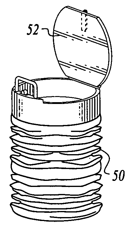
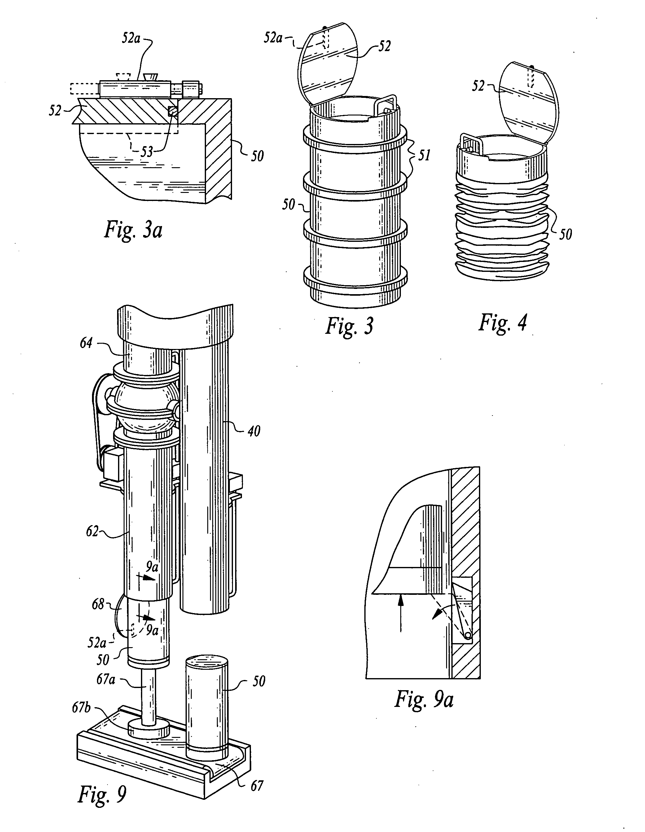
[0081]As shown in FIGS. 3-4, transport container (50) is constructed with a top end hatch (52) and a bo...

third embodiment

[0091]FIG. 14 shows elevation apparatus (10) of the present invention in an incline lifting orientation. Shaft elevation structure (20) is situated in a sloped orientation to facilitate transporting objects at an angle within chamber framework (30) on a graded incline, as opposed to in a vertical orientation. Chamber framework (30) includes a dual cavity structure (34) including return chamber (40a), delivery chamber (60), and transport container (50a) in operative communication with chamber framework (30). Return chamber (40a) includes a lower section (42) constructed and disposed to facilitate operative communication of transport container (50a) with transport channel (44) and bin (46), and additionally includes a laterally disposed ventilation channel (41), to permit air circulation within return chamber (40a) simultaneously with movement of transport container (50a) within return chamber (40a). In an alternative embodiment of the present invention (not shown), transport containe...


PUM


Abstract

The hydraulic elevation apparatus and method of the present invention incorporate a multiple chamber framework internally disposed preferably within at least one single shaft structure, which facilitates movement of object transport containers within the multiple chamber framework. Preferably, fluid elevation is employed to elevate object transport containers and their contents within the multiple chamber framework. Each single shaft structure may be constructed from an existing rehabilitated shaft, or a newly drilled shaft. The present invention may be utilized in vertical or incline lifting environments, and an auxiliary hoist chamber may be incorporated into the multiple chamber framework for use as an alternative to, or in conjunction with, elevating objects by employing fluid elevation. The present invention may be employed in a variety of heavy lifting scenarios, including underground mining or in above ground lifting environments.

Description

BACKGROUND OF THE INVENTION[0001]1. Field of the Invention[0002]The present invention generally relates to an apparatus and method for lifting objects by flotation from beneath the earth's surface or from one elevation above the earth's surface to another elevation within at least one single shaft structure. More specifically, the present invention provides an apparatus and method for conveying objects within at least one multiple chamber single shaft structure positioned beneath the earth's surface or above the earth's surface and elevating objects within the shaft structure by employing fluid buoyancy.[0003]2. Description of the Related Art[0004]A persistent and formidable challenge in mining and related industries is implementing cost effective, efficient and reliable devices and methods for lifting objects either from beneath the earth's surface or to elevations above the earth's surface. For instance, currently within the underground mining industry, demonstrably inefficient an...

Claims


Application Information

Patent Timeline
IPC IPC(8): B65G53/46
CPCE21F13/00B65G51/04
Inventor GUENTHER, ROSS
Owner GUENTHER ROSS
Why Eureka
Try Eureka