Mold Clamping Apparatus, Injection Molding Machine And Injection Molding Method

Inactive Publication Date: 2007-11-22
MITSUBISHI HEAVY INDS PLASTIC TECH +1
View PDF3 Cites 19 Cited by
  • Summary
  • Abstract
  • Description
  • Claims
  • Application Information

AI Technical Summary

Benefits of technology

[0036] According to the fifth invention, as the lateral clamping means, a hydraulic cylinder is used and the side faces of the mold are pushed by the terminal end portion of the cylinder rod. Thus, the side pusher can be made with a simple and reliable construction.
[0037] According to the sixth invention, the side pusher can be moved to the stand-by position from the predetermined lateral clamping position by the moving and positioning means so as not to obstruct the mold exchange work. Hence, even if a large size mold is used, the mold having the fixed mold and movable mold clamped together can be laterally moved without obstruction on the mold exchange.
[0038] According to the seventh invention, the side pusher has such a width directional size that the side pusher is received more on the fixed platen or movable platen side than the mold fitting face. Hence, only by moving the side pusher to the vicinity of the fixed platen or movable platen, the side pusher can be easily retracted to the stand-by position so as not to obstruct the mold exchange work.
[0039] According to the eighth invention, in addition to the function and effect of the side pusher of any one of the first to seventh inventions, as the fixed platen or movable platen, such a die plate as to comprise the wall portion forming the back face side, projection projecting from the wall portion, mold fixing portion of the terminal end of the projection and plurality of ribs connecting between the projection and wall portion. Hence, the mold clamping force clamping together the fixed platen and movable platen is conveyed to the wall portion from the mold fixing portion via t

Problems solved by technology

As this deformation quantity is small, while the thickness increase of the bumper 150 is not very problematic, there is a problem in that much work i

Method used


Image

  • Mold Clamping Apparatus, Injection Molding Machine And Injection Molding Method
  • Mold Clamping Apparatus, Injection Molding Machine And Injection Molding Method
  • Mold Clamping Apparatus, Injection Molding Machine And Injection Molding Method

Examples


first embodiment

of Mold Clamping Apparatus

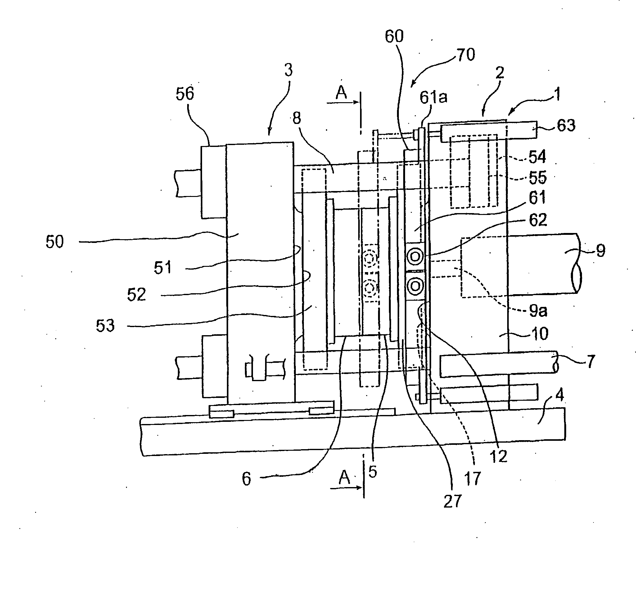
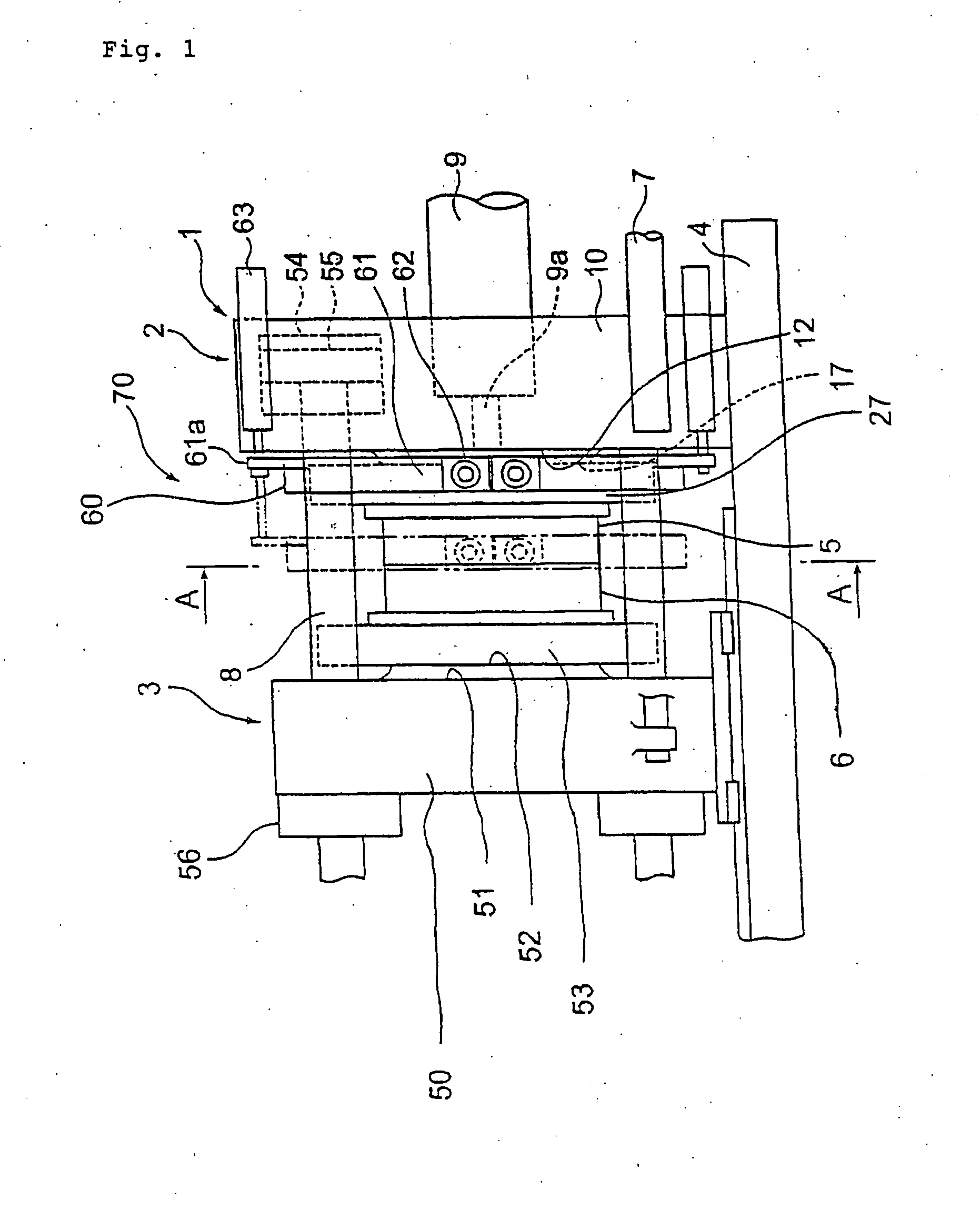
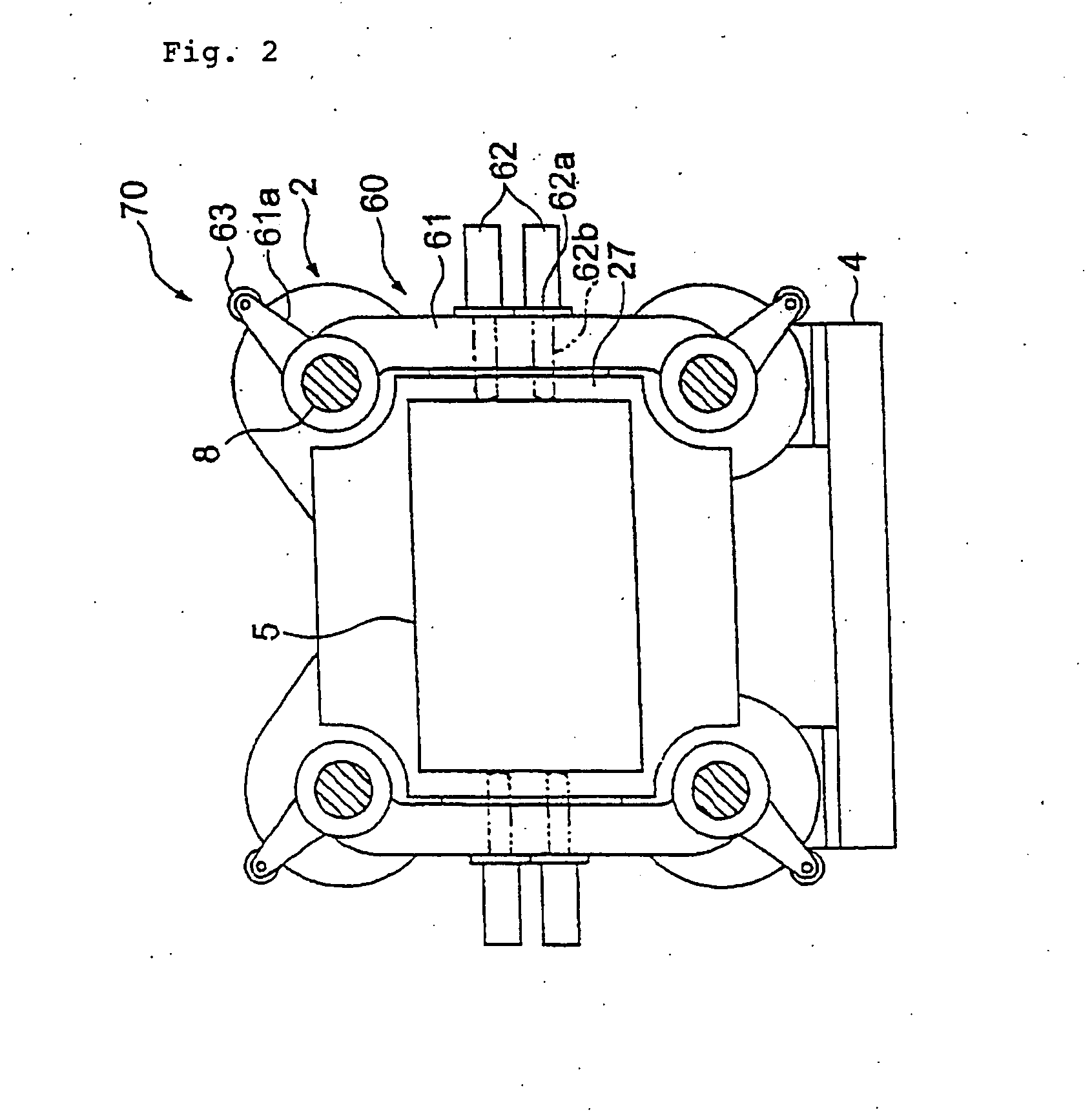
[0057]FIG. 1 is a side view showing a construction of related part of an injection molding machine comprising a first embodiment of a mold clamping apparatus according to the present invention. FIG. 2 is a cross sectional view taken on line A-A of FIG. 1.

[0058] In FIGS. 1 and 2, numeral 70 designates a mold clamping apparatus comprising a side pusher 60. A fixed platen 2 as a fixed die plate to which a fixed mold 5 is fitted is fixedly mounted on an injection unit 9 side on a base frame 4 of the injection molding machine. A movable platen 3 as a movable die plate to which a movable mold 6 is fitted is movably arranged along an axial direction of tie bars 8 (right and left directions in FIG. 1) on the base frame 4 by action of a moving cylinder 7, ball screw mechanism or the like. Also, the fixed platen 2 and movable platen 3 are constructed to be linkable to each other by the tie bars 8. A die plate 1 is thus constructed by these parts and components.

[005...

second embodiment

of Mold Clamping Apparatus

[0077] A second embodiment of a mold clamping apparatus 90 comprising a side pusher 80, different from the side pusher 60, according to the present invention will be described with reference to FIGS. 3 to 5. FIG. 3 is a side view showing a construction of related part of an injection molding machine comprising the second embodiment of the mold clamping apparatus. FIG. 4 is a plan view of the part shown in FIG. 3. FIG. 5 is a cross sectional view taken on line B-B of FIG. 3.

[0078] The side pusher 80 is appropriate specifically for use as a large size mold clamping apparatus. As the construction of a body part of the mold clamping apparatus 90 is approximately the same as that of the mold clamping apparatus 70, the same or similar parts and components are given with the same reference numerals and description thereof will be omitted.

[0079] In the figures, numeral 2 designates a fixed platen that has its lower end fixed to a base frame 4, numeral 3 a movable...


PUM

PropertyMeasurementUnit
Sizeaaaaaaaaaa
Widthaaaaaaaaaa
Deformation enthalpyaaaaaaaaaa

Abstract

Provided is a mold clamping apparatus of a mold having a side wall portion of cantilever shape, by which deformation of the mold side wall portion can be efficiently suppressed. An injection molding machine and injection molding method both using the mold clamping apparatus are also provided. Thereby, molded articles with high quality having no flash generation can be obtained. The mold clamping apparatus comprises a side pusher comprising a pair of supports respectively arranged between adjacent two tie bars out of a plurality of tie bars at positions symmetrical to each other and slidably supported to the tie bars, a moving and positioning means linking the supports to a fixed platen or movable platen and moving the supports to be positioned at a predetermined position and a lateral clamping means provided on each of the pair of supports to push a side face of a fixed mold or movable mold.

Description

TECHNICAL FIELD [0001] The present invention relates to a mold clamping apparatus used for an injection molding machine, die casting machine or the like that has a pair of molds to be opened and closed for producing molded articles as well as relates to an injection molding machine and injection molding method both using the mold clamping apparatus. BACKGROUND OF THE INVENTION [0002]FIG. 12 shows a mold clamping apparatus used for a prior art injection molding machine. In the figure, a mold clamping apparatus 101 comprises a base frame 102, fixed die plate (platen) 105 fixedly mounted on the base frame 102 and fitted with a fixed mold 103, movable die plate (platen) 111 movably provided in the right and left directions in the figure on a rail 107 by action of a hydraulic cylinder 113 and plurality of tie bars 115 that can link together the fixed die plate 105 and movable die plate 111. The fixed die plate 105 has therein a hydraulic cylinder 117 for mold clamping concentrically prov...

Claims


Application Information

Patent Timeline
IPC IPC(8): B29C45/64
CPCB22D17/266B29C2045/1788B29C45/6728B29C45/1744
Inventor MATSUSHITA, HIROTOTERAYAMA, HIROSHIKATOH, NAOKISAKAMOTO, AYUMIYASUDA, SHINJIMORI, SADAO
Owner MITSUBISHI HEAVY INDS PLASTIC TECH
Why Eureka
Try Eureka