Fuel Injection Valve For Internal Combustion Engine

Inactive Publication Date: 2007-11-29
BOSCH CORP
View PDF4 Cites 3 Cited by
  • Summary
  • Abstract
  • Description
  • Claims
  • Application Information

AI Technical Summary

Benefits of technology

[0008] The nozzle needle is supported and guided in the guide hole such that the nozzle needle is movable in an axial direction inside the guide hole. The gap between the nozzle needle and the guide hole is extremely narrow, and high-pressure fuel of a high-pressure portion of the leading end of the nozzle needle slightly leaks through the gap to a low-pressure portion at the nozzle holder side. At least part of the gap is tapered, and the gap has a form including a portion that widens like a skirt from the high-pressure portion to the fuel low-pressure portion. As a result

Problems solved by technology

Consequently, there is the problem that, depending on the running condition of the engine, as when the engine is started in a low temperature atmosphere such as −20° C. or below, the wax mixed into the fuel is deposited in portions of the fuel injection valve and causes various problems.
Particularly when the wax is deposited in a fuel leak passage for allowing the fuel to escape from t

Method used


Image

  • Fuel Injection Valve For Internal Combustion Engine
  • Fuel Injection Valve For Internal Combustion Engine
  • Fuel Injection Valve For Internal Combustion Engine

Examples


Example

[0013] The present invention will now be described in greater detail in accordance with the attached drawings.

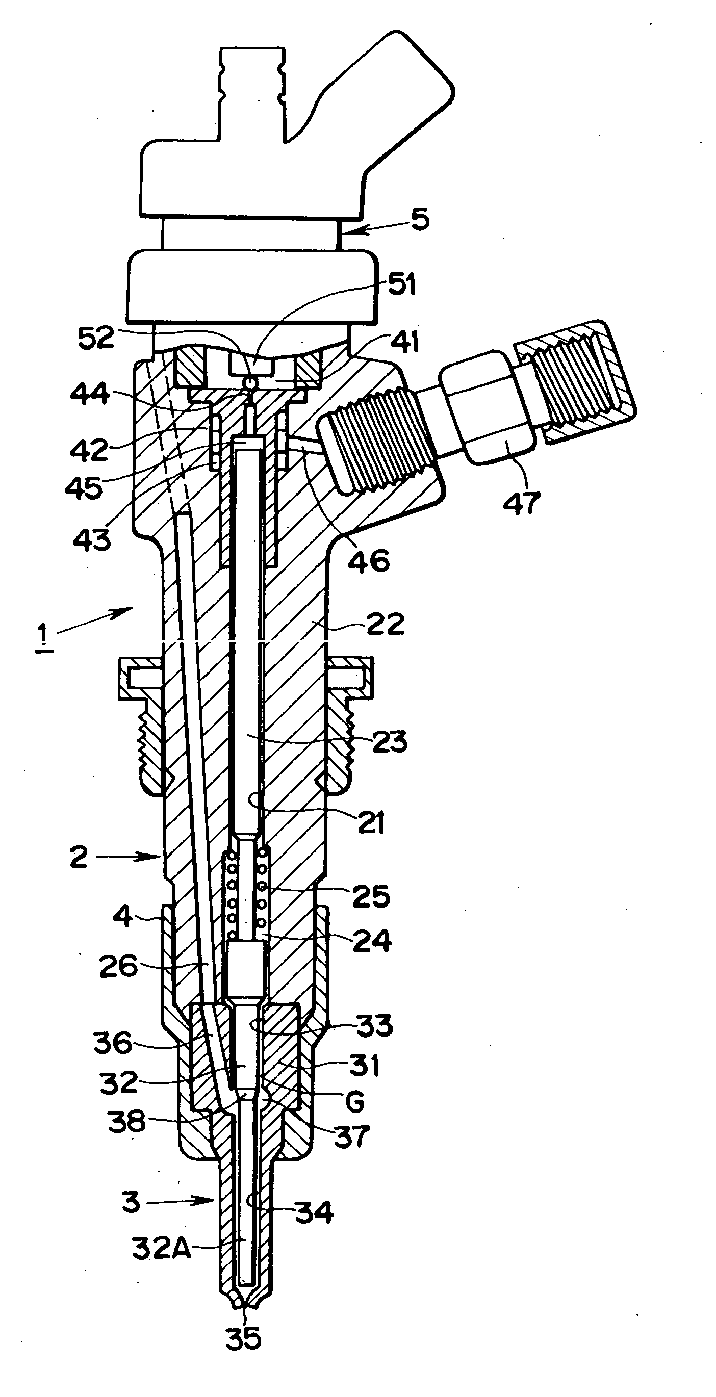
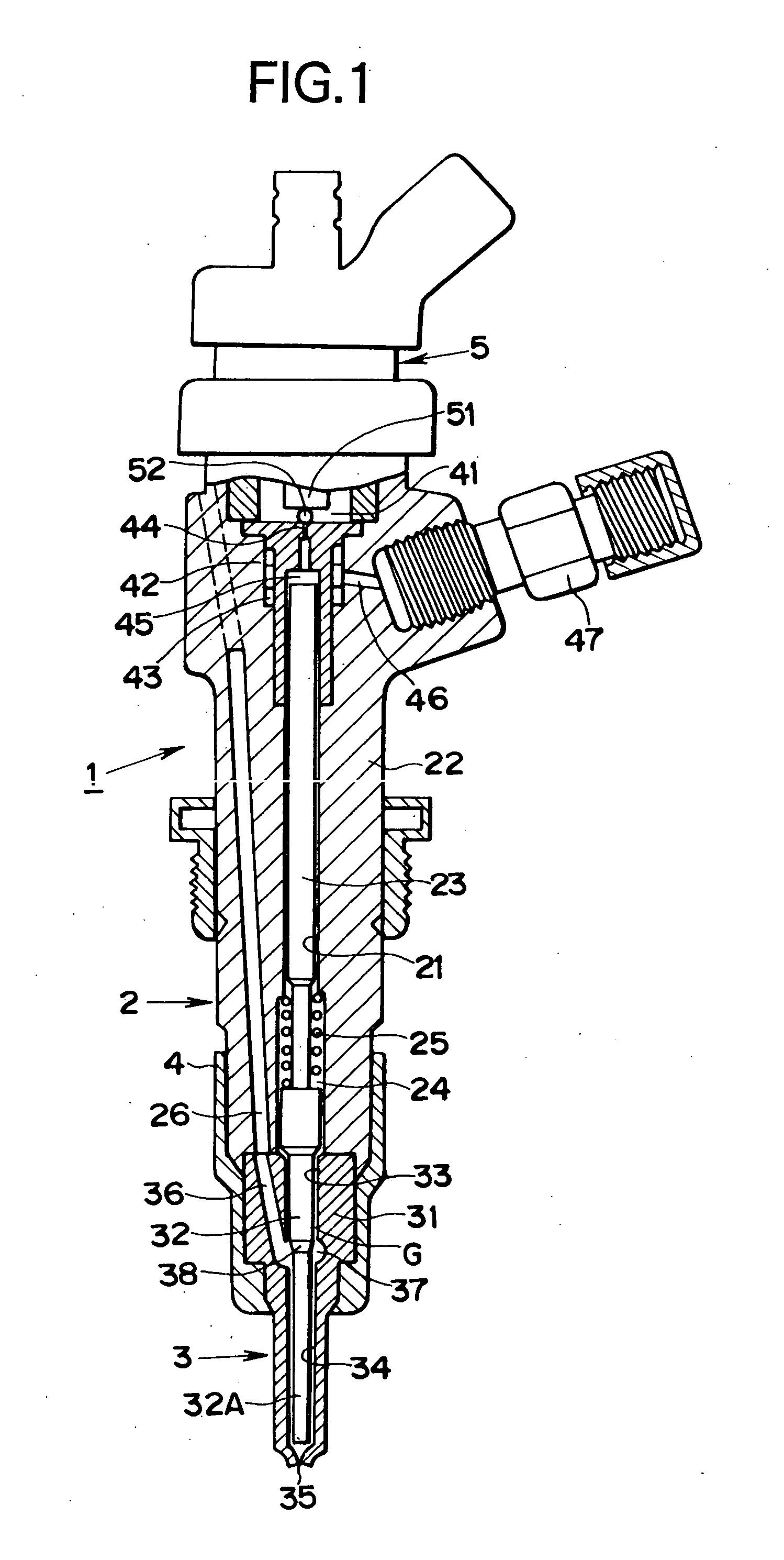
[0014]FIG. 1 is a cross-sectional view showing an example of an embodiment of a fuel injection valve according to the present invention. That which is represented by reference numeral 1 is a fuel injection valve for an internal combustion engine used in the Common Rail System for injecting / supplying fuel to a diesel internal combustion engine. The fuel injection valve 1 is attached to a cylinder of an unillustrated diesel internal combustion engine, is for directly injecting / supplying, to the inside of the cylinder and at a required timing, just the required amount of high-pressure fuel supplied from an unillustrated common rail, and comprises a nozzle 3 fixed to the leading end of a nozzle holder 2 with a retaining nut 4. An electromagnetic valve 5 is disposed on a trailing end of the nozzle holder 2.

[0015] The nozzle holder 2 includes a hollow body 22 in which a guide ho...


PUM


Abstract

In order to ensure that operation does not become unstable even when a wax component included in fuel solidifies, in a fuel injection valve (1) comprising a nozzle (3) fixed to a leading end portion of a nozzle holder (2), with the nozzle (3) being configured such that a nozzle needle (32) inserted into a guide hole (33) inside a nozzle body (31) is guided by the guide hole (33) and moves in an axial direction to open/close an injection hole (35), a tapered portion (33B) that widens toward the nozzle holder (2) is disposed in the guide hole (33). Thus, when the component included in the fuel solidifies, the solidified matter can be speedily discharged from a gap (G) serving as a fuel leak passage formed between the nozzle needle (32) and the guide hole (33).

Description

TECHNICAL FIELD [0001] The present invention relates to a fuel injection valve for directly injecting / supplying fuel to the inside of a cylinder of an internal combustion engine. BACKGROUND ART [0002] As a fuel injection valve for directly injecting / supplying fuel to the inside of a cylinder of an internal combustion engine such as in the Common Rail System, a fuel injection valve of the type disclosed in JP-A-7-310621, for example, is known. This fuel injection valve is configured such that an electromagnetic valve is powered and opened so that a control chamber inside the body of the fuel injection valve becomes communicated with a low-pressure portion, whereby the back pressure of a valve piston is removed, a nozzle needle is lifted, fuel injection is initiated, the powering of the electromagnetic valve is stopped after the elapse of a predetermined amount of time, and the communicated state between the control chamber and the low-pressure portion is released, whereby predetermin...

Claims


Application Information

Patent Timeline
IPC IPC(8): F02M61/16F02M61/10F02M61/12
CPCF02M61/12F02M55/002F02M2200/07F02M61/10F02M61/16
Inventor NOZAKI, HIROAKIMATSUZAKI, KIYOSHI
Owner BOSCH CORP
Why Eureka
Try Eureka