Continuously Variable Transmission

Active Publication Date: 2007-11-29
NSK LTD
View PDF3 Cites 26 Cited by
  • Summary
  • Abstract
  • Description
  • Claims
  • Application Information

AI Technical Summary

Benefits of technology

[0048]In addition, as is described in the twelfth aspect of the invention, in the event that the construction is adopted which includes the mode which can realize the geared neutral state in which the output shaft is stopped while the input shaft is allowed to be kept rotating in one direction, the mode switch between the low-speed mode and the high-speed mode is performed at low speed. Consequently, the transmission ratio of the toroidal continuously variable transmission is made easy to reach the mode switching point every time the vehicle repeats start and stop, and the necessity of performing the mode switch quickly and smoothly is increased, in which circumstances the advantage of the invention can be obtained more remarkably.

Problems solved by technology

However, in the case that the clutch which had been in disengagement until then is started to be engaged on condition that the transmission ratio of the toroidal continuously variable transmission has reached the mode switching point in the way described above, the time period that is taken to perform the mode switch becomes long.
Namely, when the modes are switched, the low-speed and high-speed clutches which make up the clutch device take a certain time period (cause a delay in responding to oil pressure) from the start to the end of engagement thereof in accordance with conditions at the time of switching such as oil temperature and temperature characteristics of friction materials which make up each of the clutches and furthermore based on an unavoidable delay in mechanical response.
On the other hand, when the modes are switched, a change-speed control according to the mode which results after the intended mode switch is completed cannot be started before the engagement of the clutch which had been in disengagement until then is completed.
Then, when the time period required for the mode switch is extended, there might be caused a possibility that an acceleration intended by the driver cannot be obtained sufficiently (or the acceleration performance is reduced) when the vehicle is attempted to be started drastically from rest (or accelerated drastically), for example, by largely depressing the accelerator pedal (by increasing the throttle position) or when the vehicle is attempted to accelerated drastically based on a kickdown operation during the running of the vehicle, which is not preferable.

Method used


Image

  • Continuously Variable Transmission
  • Continuously Variable Transmission
  • Continuously Variable Transmission

Examples


Embodiment Construction

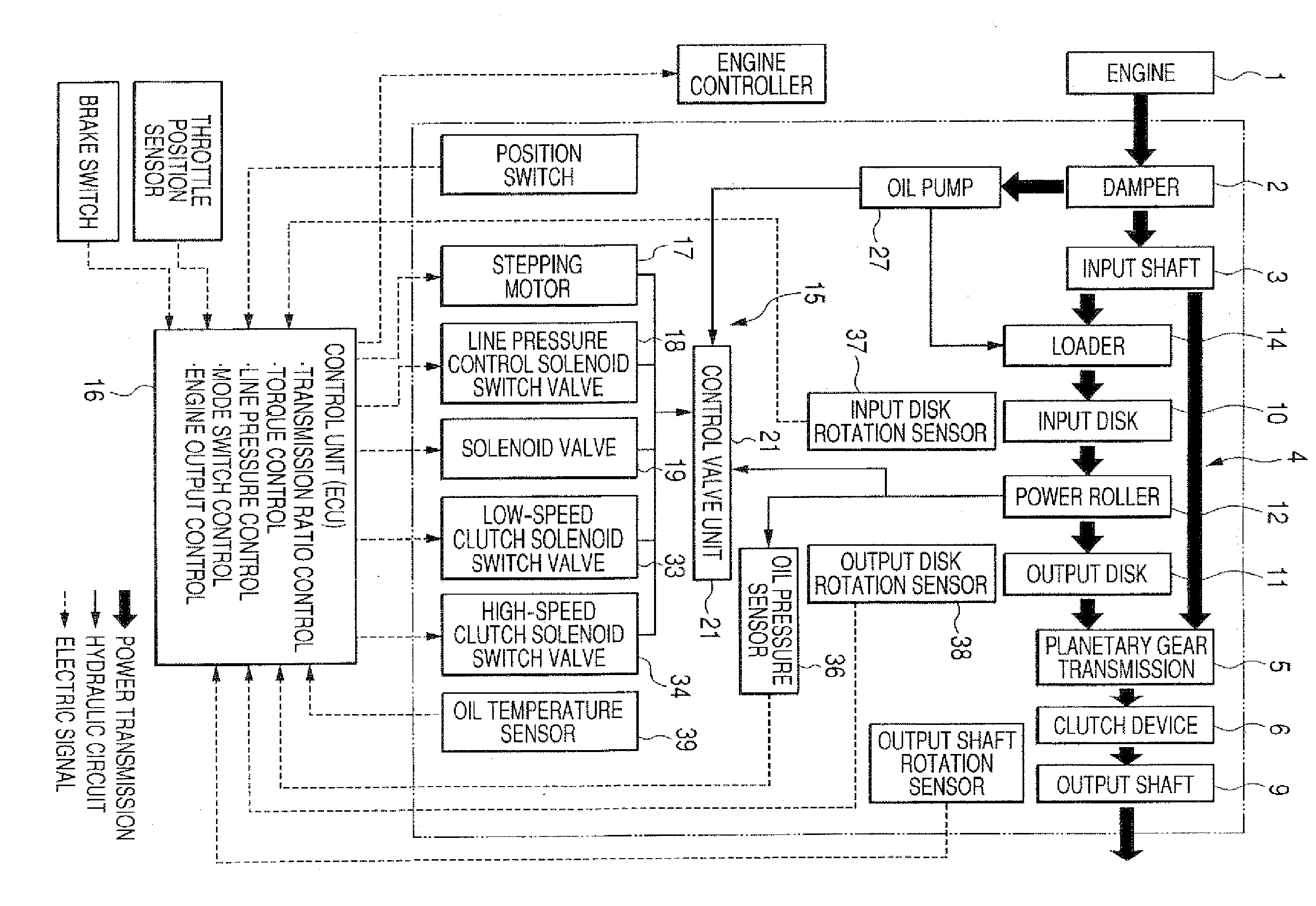
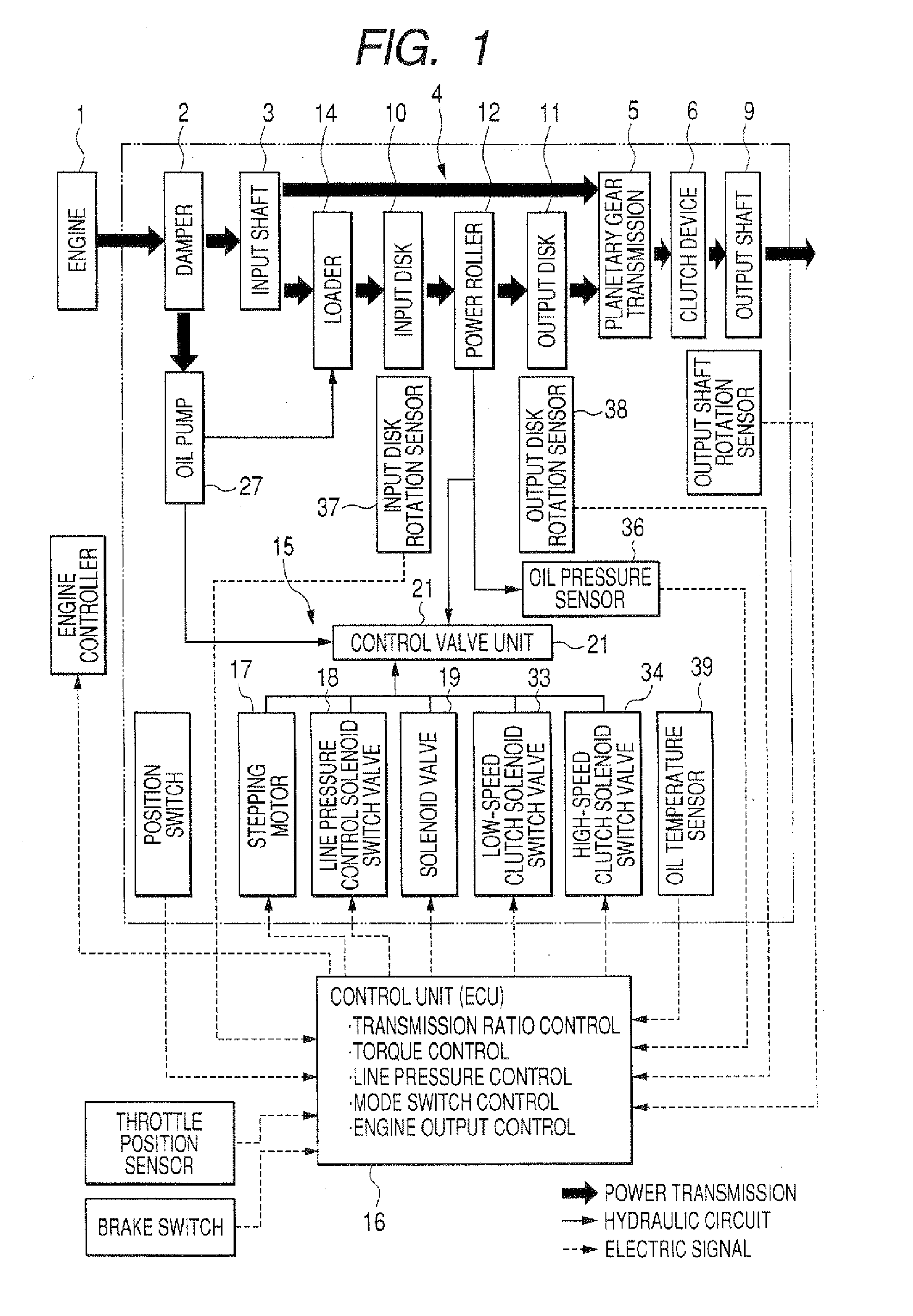
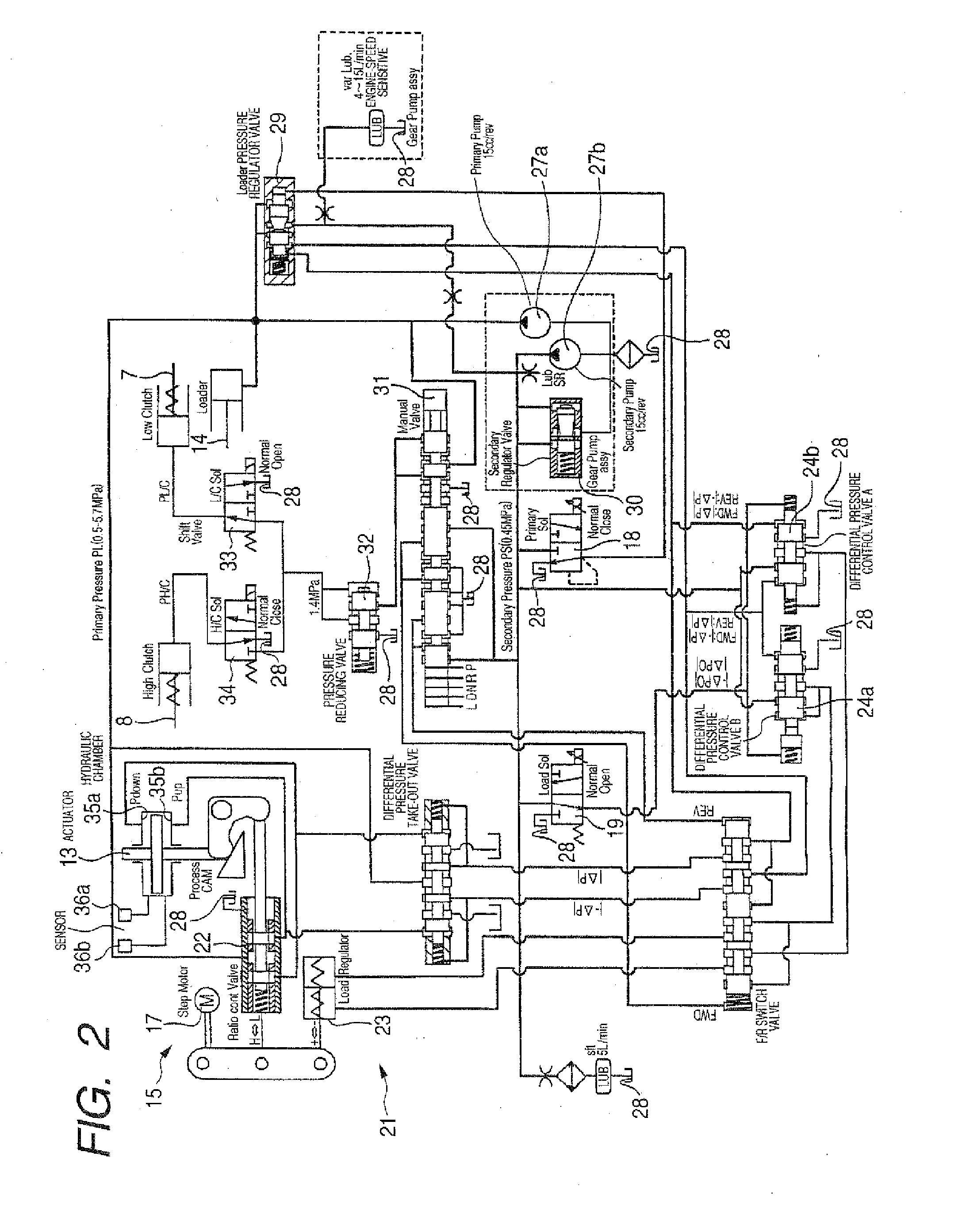
[0061]FIGS. 1 to 6 depict an embodiment of the invention. The feature of this embodiment resides in the point that a time period substantially necessary for performance of a mode switch between a low-speed mode and a high-speed mode (a time period during which no speed change takes place in a toroidal continuously variable transmission 4) is prevented from being extended by devising a timing to start the engagement of one of clutches (a low-speed clutch 7 or a high-speed clutch 8) which had been in disengagement until then so as to perform the mode switch quickly and smoothly. Since the construction and function of the other portions of the embodiment are similar to those of the conventional construction which is depicted in FIGS. 9 to 10, here, the description thereof will be omitted for no repetition thereof or will be made only briefly, and characteristic portions of this embodiment will mainly be described below. Note that in the case of this embodiment, a relationship between t...


PUM


Abstract

A control unit is imparted a function in which the engagement of a high-speed clutch which had been in disengagement until then is started (or the energization of a high-speed clutch solenoid switch valve is put to ON) before a change-speed of a toroidal continuously variable transmission has reached an optimal value for performance of a mode switch (a point A, for example, 0.46 in a speed increasing ratio) or at a point B (for example, 0.6 in the speed increasing ratio). As a result of this, the problem can be solved.

Description

BACKGROUND OF THE INVENTION[0001]1. Field of the Invention[0002]The present invention relates to an improvement on a continuously variable transmission which incorporates therein a toroidal continuously variable transmission for use as an automatic transmission for, for example, a vehicle (a motor vehicle), which realizes at low cost a construction which enables a quick and smooth mode switching between a low-speed mode and a high-speed mode.[0003]2. Description of Related Art[0004]The application of a toroidal continuously variable transmission to an automotive transmission is known as it is described in many publications such as Japanese Patent Examined Publication JP-B-2734583, Japanese Patent Unexamined Publication JP-A-5-39850, “supplement volume to Red Badge Series 245 / A Book Teaches Latest Mechanisms of Motor Vehicles” pages 92 to 93 written by Motoo Aoyama and published by Sansuisha Co., Ltd. / Kodansha Co., Ltd. on Dec. 20, 2001, and “Toroidal CVT” written by Hlirohisa Tanaka...

Claims


Application Information

Patent Timeline
IPC IPC(8): F16H37/02
CPCF16H37/086F16H2306/20F16H2061/6609F16H61/6648
Inventor SINOJIMA, TAKUMIINOUE, EIJI
Owner NSK LTD
Why Eureka
Try Eureka