Database system with multiple processing nodes

a database system and processing node technology, applied in the field of database system database operations, can solve the problems of inability to achieve the same data, so as to reduce time and space requirements, the effect of less spa

a database system and processing node technology, applied in the field of database system database operations, can solve the problems of inability to achieve the same data, so as to reduce time and space requirements, the effect of less spa

US20070276788A1Inactive Publication Date: 2007-11-29KOGNITIO

Image

  • Database system with multiple processing nodes
  • Database system with multiple processing nodes
  • Database system with multiple processing nodes

Examples


Embodiment Construction

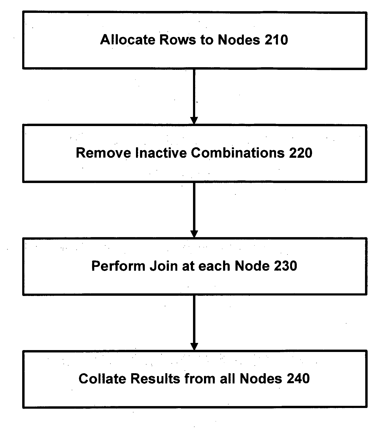
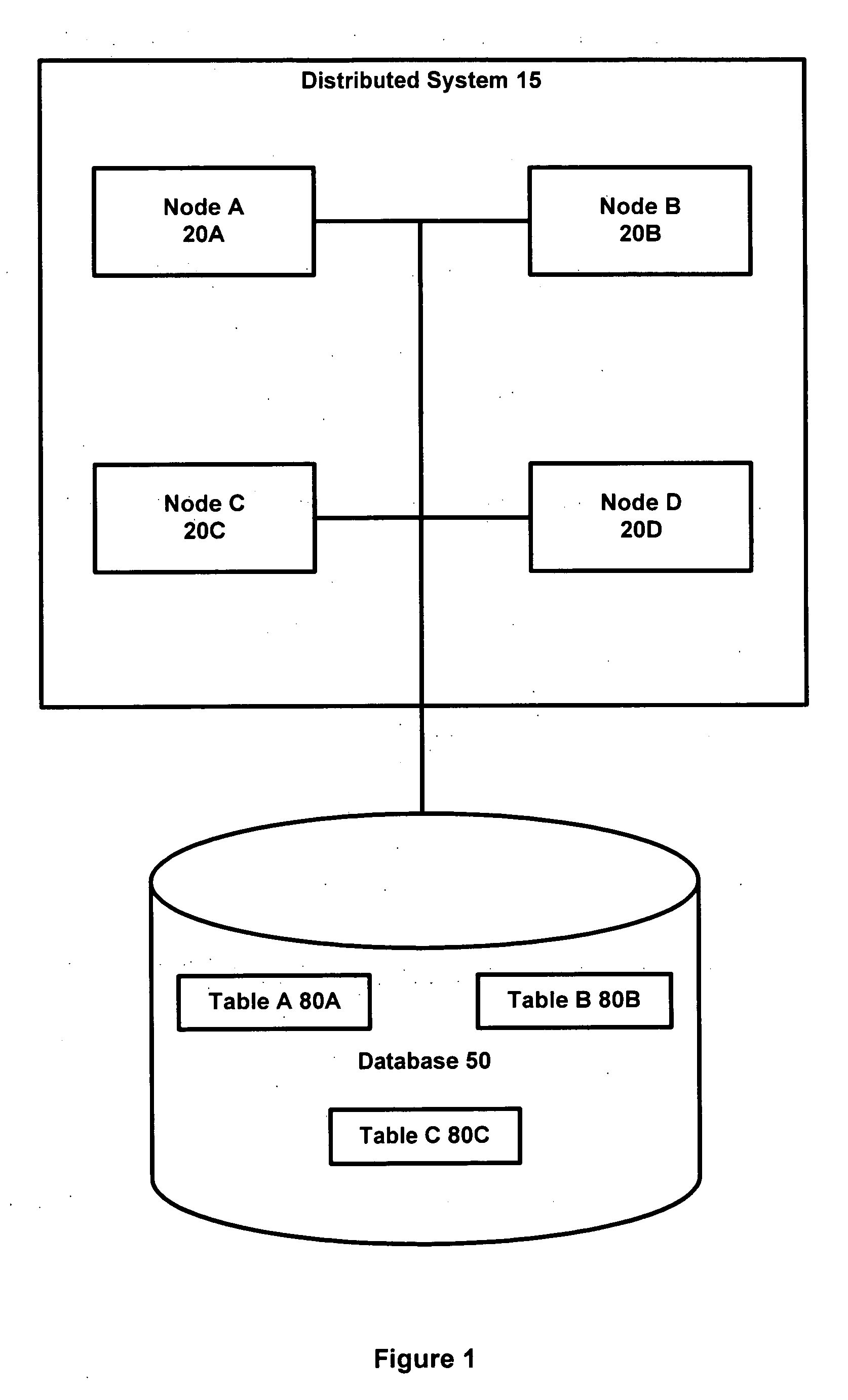
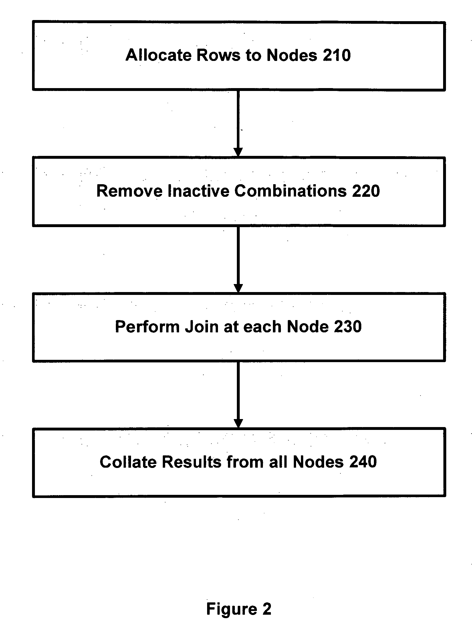
[0038] In accordance with one embodiment of the invention, we define two new distributions, horizontal-p and vertical-p, where p may be chosen according to the relative sizes of table A and table B, and generally 1≦p≦√n. In one implementation, p=√(n|A| / |B|) (for reasons that are explained below) but other values for p may be used if more convenient. For example, a different value for p might be used to allow p to divide n exactly, or to match the distribution of an existing table, or if the rows of A and B have very different sizes (as explained in more detail below). Note that table A and B may each be too large to fit into the memory of a single node.

[0039] A value of q is chosen such that q=int(n / p). The first pq nodes are then labelled as:

N11,N12, . . . ,N1p,

N21,N22, . . . ,N2p,

. . .

. . .

Nq1,Nq2, . . . ,Nqp

The remaining r=n mod p (

[0040] We define the “horizontal groups” as Hi={Nij|1≦j≦p}, that is, the rows

in the table above,...


PUM


Abstract

A method and apparatus are provided for distributing a database join operation across a plurality of processing nodes. The database join operation is performed between a first table having M1 rows and a second table have M2 rows and involves forming M1×M2 combinations of rows from the first and second tables. The method includes allocating across the plurality of processing nodes the M1×M2 combinations of rows from the first and second tables. Each of the M1×M2 combinations is present on one of the nodes, and each node stores combinations corresponding to a subset of the M1 rows from the first table and a subset of the M2 rows from the second table. The method further comprises performing for each processing node the join operation in respect of all combinations of rows allocated to that processing node and collating results across all the processing nodes to complete the join operation.

Description

FIELD OF THE INVENTION [0001] The present invention relates to performing database operations in a database system having multiple processing nodes. BACKGROUND OF THE INVENTION [0002] A common operation on a relational database is to join two tables (relations): A={a1, a2, . . . , an} and B={b1, b2, . . . , bm}, where |A|≦|B|. Notionally, this is achieved by firstly forming the Cartesian product of the two tables to produce a table T=A×B={aibj|aiεA, bjεB}. Thus if A contains I tuples and N attributes and B contains J tuples and M attributes, T contains (I*J) tuples and (N+M) attributes. Secondly, we apply the join condition θ to each row in T, eliminating rows that do not match to form a result table J={Ti|θ(Ti)}. [0003] As an example of a join operation, table A may represent a listing of customers, complete with customer name, number and address, while table B may represent a listing of pending orders, with order number, product, and customer number. In this example, the join oper...

Claims


Application Information

Patent Timeline
29 Nov 2007
Publication
US20070276788A1
IPC
G06F17/30
CPC
G06F17/30498; G06F16/2456
Inventors
COHEN, BEN