Penetrometer with electronically-controlled hammering module

a penetrometer and electronic control technology, applied in the field of improved penetrometer devices, can solve the problems of heavy equipment, many disadvantages of the prior art, fatigue of the human operator, etc., and achieve the effect of increasing the hammering rate and increasing the impa

Inactive Publication Date: 2007-12-06
ZACNY KRZYSZTOF A +1
View PDF0 Cites 16 Cited by
  • Summary
  • Abstract
  • Description
  • Claims
  • Application Information

AI Technical Summary

Benefits of technology

[0009]In the present invention, an electronically- controlled hammering module is used to apply a repetitive hammering force under electronic control to the top end of a penetrometer rod. In a preferred embodiment, the hammering module has a battery-powered percussive hammer that sits on top of the rod which, when activated, applies an electrically-generated impulse hammering force to the top of the rod. The hammering force is generated by electrically driving a small mass, e.g., of approximately 100 gm, at a controlled rate, e.g., of 5-50 Hz. The faster the rate of hammering, the more impact applied, so higher rates are used for stronger soils and lower rates for weaker soils. This application of force causes the cone-shaped point of the rod to penetrate into the soil at a controlled rate that is correlated with the strength of the soil. Therefore in this constant penetraton mode, the impact energy is correlated to the soil strength.

Problems solved by technology

The entire device is heavy and must be mounted on a trailer or other wheeled vehicle.
The disadvantages of the prior art are many.
For the DCP device, repeated manual lifting of the sliding hammer causes fatigue on the part of the human operator (which in turn reduces the accuracy of the measurement because tired operator doe not lift the hammer all the way to the top) and / or requires multiple operators to avoid fatigue.
Operators frequently injure themselves by getting pinched by the sliding hammer.
Operators also require hearing protection because individual hammer blows are very noisy.
The quality of the measurements is compromised by operator error in manually taking the depth measurements, particularly in cases where fatigue has set in.
This extra information makes the process more time consuming.
However, operators without proper training may not be able to identify when the smaller hammer should be used.
Furthermore, changing from one hammer to another is cumbersome and time consuming.
Also, for extremely weak soils, the lighter hammer is still too heavy to produce the best possible results.
The pressure wave developed in the device may also break the braze between the rod and the hammer assembly making the device useless.
For the ADCP device, the main disadvantage is the large size and mass of the unit.
It must be mounted on a trailer or a small truck and this restricts the locations where it can be used.
It also has the same disadvantages as the DCP device with regard to changing hammers and providing accurate measurements in very weak soils.

Method used


Image

  • Penetrometer with electronically-controlled hammering module
  • Penetrometer with electronically-controlled hammering module

Examples


Embodiment Construction

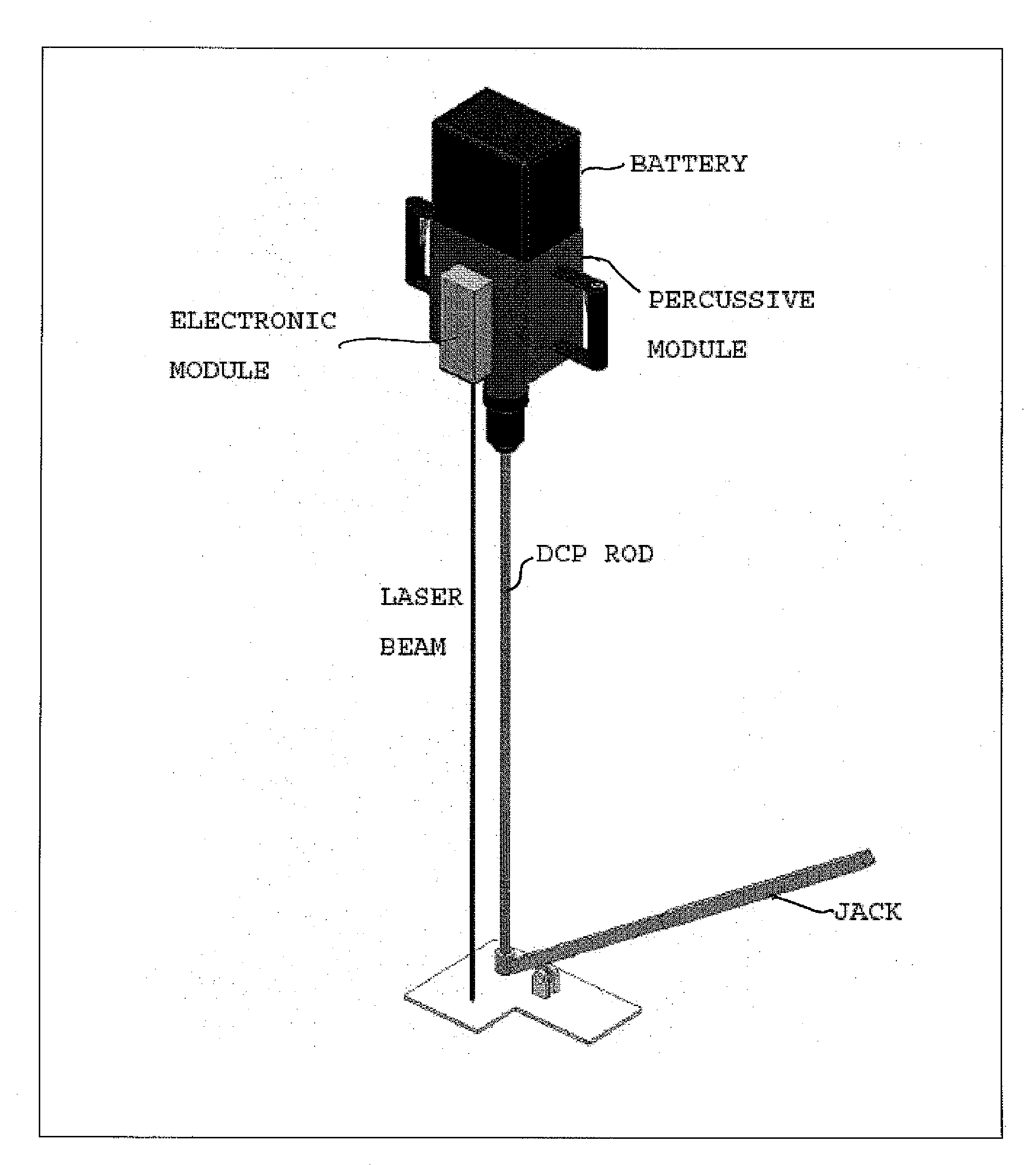
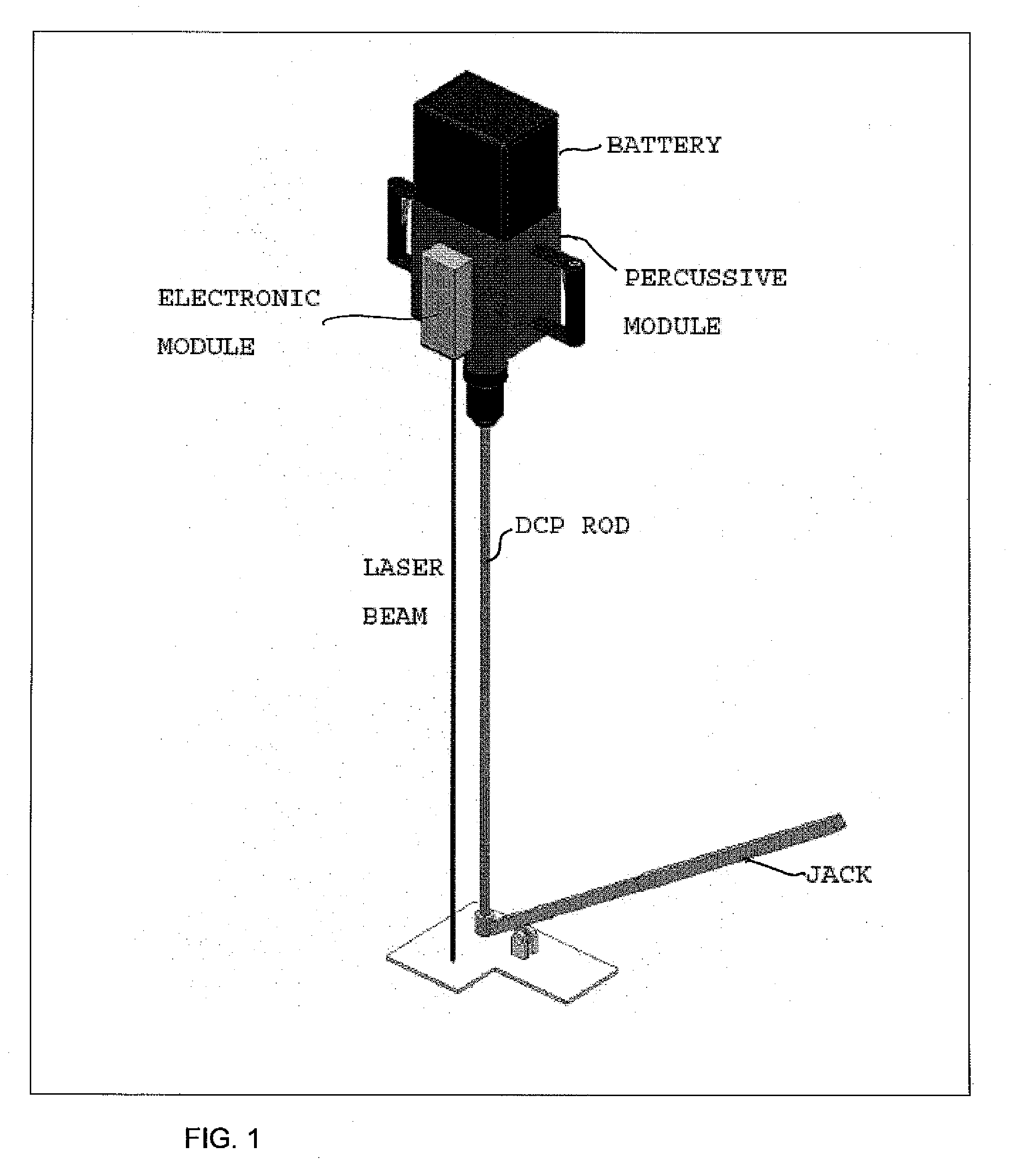
[0011]FIG. 1 shows a schematic perspective view of a penetrometer with an electronically-controlled hammering module in accordance with the present invention. The hammering module applies a controlled hammering force to the top of a driven end of a long, rigid rod having an opposite ground piercing end, referenced in the figure as a dynamic cone penetrometer (DCP) rod, to drive its ground-piercing end into the ground. In a preferred embodiment adapted for field use, the hammering module includes an electronic (control) module, a battery as a power source, and a percussive module for applying a controlled and repetitive percussive hammering force to the top of the rod. A jack is used to facilitate removal of the rod from the ground.

[0012]The application of the hammering force causes the cone-shaped point of the DCP rod to penetrate into the soil at a controlled rate that is correlated with the strength of the soil. The depth of penetration is determined by noting the decrease in dist...


PUM

PropertyMeasurementUnit
hammering forceaaaaaaaaaa
heightaaaaaaaaaa
strengthaaaaaaaaaa

Abstract

An electronically-controlled hammering module is used to apply a repetitive hammering force under electronic control to the top end of a dynamic cone penetrometer rod. In a preferred embodiment, the hammering module has a battery-powered percussive hammer that applies an electrically-generated impulse hammering force to the top of the rod. The depth of penetration is measured with a range-finder and used to compute the rate of penetration of the rod into the ground and correlated to the strength of the soil. The rate of hammering is controlled to cause the rod to penetrate into the soil at a controlled rate correlated with the strength of the soil.

Description

[0001]This U.S. patent application claims the priority of U.S. Provisional Application No. 60 / 804076 filed on Jun. 6, 2006, entitled “Percussive Cone Penetrometer and Accelerated Cone Penetrometer”, of the same inventors.[0002]The subject matter herein was developed for ERDC as part of the “Rapid In-Situ Soil Characterisation System”, funded through the Department of Defense SBIR Phase I program. The U.S. Government retains certain rights in the invention.TECHNICAL FIELD[0003]This invention relates to an improved penetrometer device for applying a hammering impulse force to drive a rod into the ground to a desired level.BACKGROUND OF INVENTION[0004]A penetrometer is used for performing soil strength measurements in the field. The measurements obtained can be correlated with the engineering soil strength parameter such as the California Bearing Ratio (CBR), a widely accepted standard in civil engineering, or possibly with a physical soil strength parameter, such as a soil bearing str...

Claims


Application Information

Patent Timeline
Patent Type & Authority Applications(United States)
IPC IPC(8): G01N3/40E02D1/00
CPCG01N3/48E02D1/022
Inventor ZACNY, KRZYSZTOF A.GLASER, DAVID
Owner ZACNY KRZYSZTOF A
Why Eureka
Try Eureka