Optical deflector and optical instrument using the same

a technology which is applied in the field of optical deflector and optical instrument, can solve the problems of not easy to set plural natural oscillation modes in a desired relationship, not easy to keep the displacement angle stable, etc., and achieves the effect of large but stable displacement angle, easy adjustment, and stable displacement angl

Inactive Publication Date: 2007-12-06
CANON KK
View PDF14 Cites 18 Cited by
  • Summary
  • Abstract
  • Description
  • Claims
  • Application Information

AI Technical Summary

Benefits of technology

[0014]In accordance with the present invention, the moment of inertia of the second movable element or the length thereof in a direction perpendicular to the oscillation axis is set as described above. This accomplishes an optical deflector in which plural natural oscillation modes of the optical deflector can be easily adjusted into a desired relationship and, furthermore, even if the displacement angle is relatively large, the displacement angle is held stable. In an optical instrument using this optical deflector, a large but stable displacement angle is accomplished by the present invention.

Problems solved by technology

However, in optical deflectors having plural movable elements and plural torsion springs, due to dispersion of process precision or the like, it is not easy to set plural natural oscillation modes in a desired relationship.
Furthermore, if the displacement angle of the optical deflector is large, because of air resistance or the like, it is not easy to keep the displacement angle stable.

Method used


Image

  • Optical deflector and optical instrument using the same
  • Optical deflector and optical instrument using the same
  • Optical deflector and optical instrument using the same

Examples


first working example

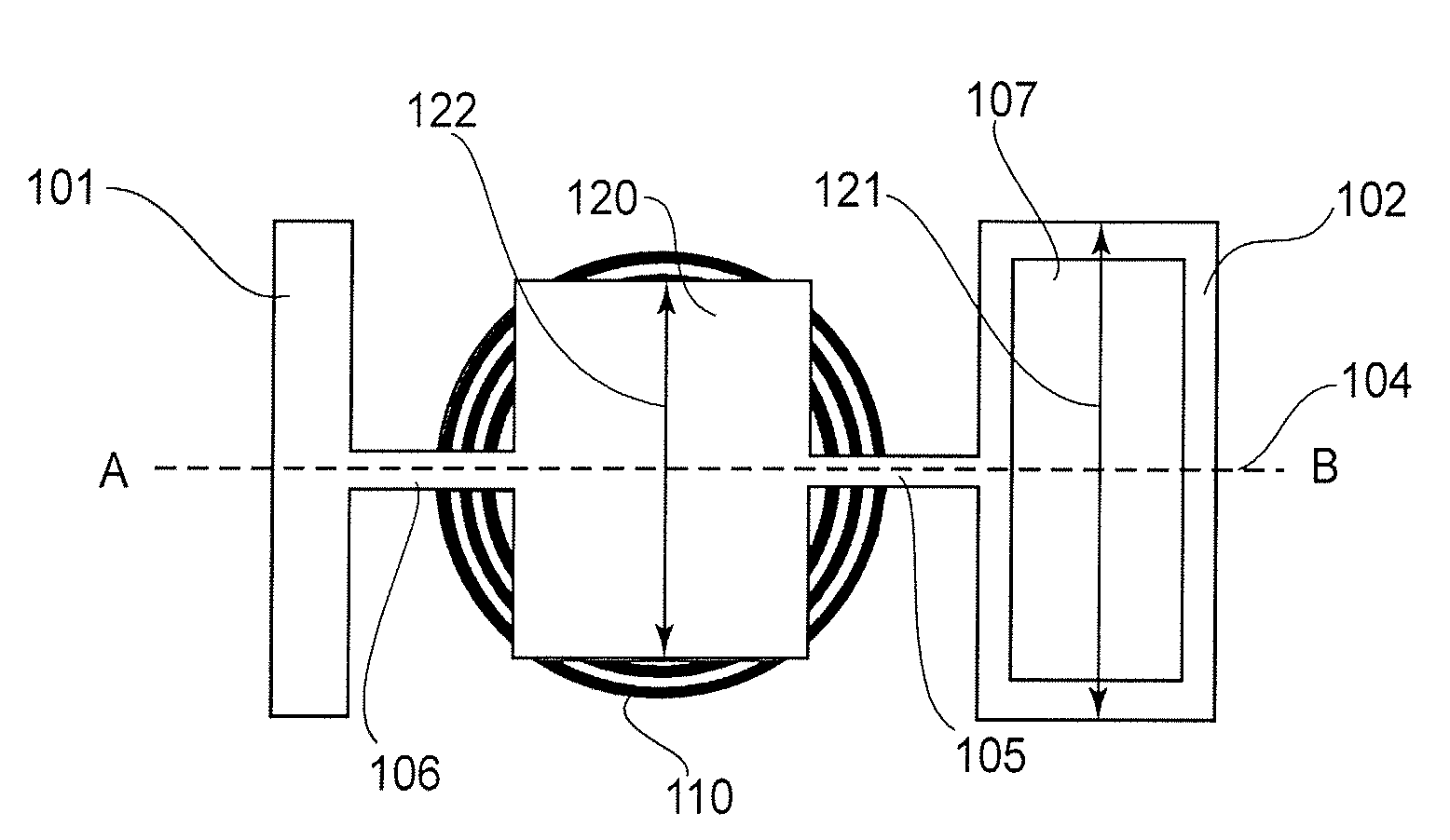
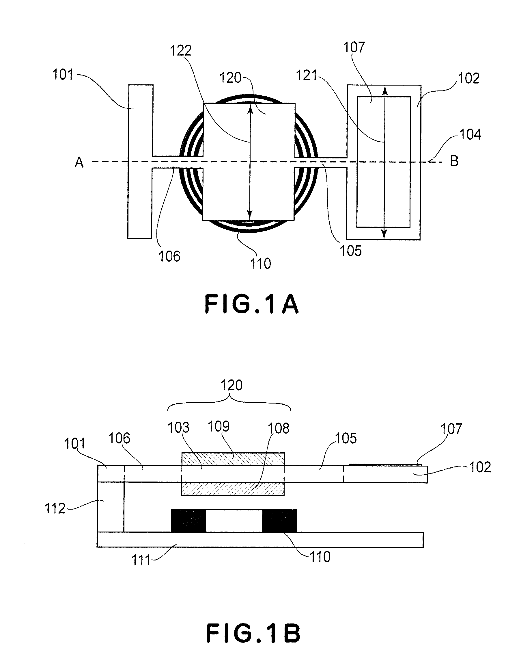
[0064]A first working example of the present invention will be described below. This working example directly corresponds to the embodiment described above. FIGS. 1A and 1B show the structure of an optical deflector according to the first working example. FIG. 1A is a plan view of the optical deflector, and FIG. 1B is a section taken along a line A-B in FIG. 1A. The optical deflector comprises a supporting member 101, a first movable element 102 having a reflection surface 107, a second movable element 120, and torsion springs 105 and 106 for resiliently coupling the supporting member 101, first movable element 102 and second movable element 120 about an oscillation axis 104. The optical deflector further comprises a driving unit for applying a torque to the second movable element 120 to produce resonance drive of the first and second movable elements 102 and 120, and a drive control unit for controlling the driving unit. The driving unit includes a magnet 108 disposed at the second...

second working example

[0085]Next, an optical deflector according to a second working example of the present invention will be described with reference to FIGS. 4A and 4B. FIG. 4A is a plan view of the optical deflector of this example, and FIG. 4B is a section taken along a line A-B in FIG. 4A. The optical deflector of the second working example has a generally similar structure as the deflector of the first working example but, in this working example, it includes two second movable elements 220a and 220b as well as torsion springs 205a, 205b, 206a and 206b for resiliently connecting a first movable element 202 having a reflection surface 107 with the second movable elements 220a and 220b, about an oscillation axis 204. The second movable elements 220a and 220b have silicon portions 203a and 203b and film-like permanent magnets 208a and 028b, respectively.

[0086]The optical deflector of this working example has a feature that the second movable elements 220a and 220b have a thickness larger than the firs...

third working example

[0090]Referring to FIGS. 5A and 5B, an optical deflector according to a third working example will be described. FIG. 5A is a plan view of the optical deflector of this example, and FIG. 5B is a section taken along a line A-B in FIG. 5A. The optical deflector of the third working example has a generally similar structure as the deflector of the first working example, but it is different from the first working example in that a second movable element 320 resiliently connected to a supporting member 301 through a torsion spring 306 has a silicon portion 303 and hard magnetic materials 308a and 308b. These hard magnetic materials 308a and 308b are a Fe—Cr—Co magnet in this example.

[0091]The second movable element 320 of the optical deflector of this working example is equipped with a plurality of hard magnetic materials such as at 308a and 308b which are disposed sandwiching the oscillation axis 304 therebetween. Since the hard magnetic materials 308a and 308b are made of Fe—Cr—Co havi...


PUM


Abstract

An optical deflector includes a supporting member, a first movable element having a light deflecting element, at least one second movable element, at least one first torsion spring configured to support the first and second movable elements, for torsional oscillation about an oscillation axis, at least one second torsion spring configured to support the second movable element and the supporting member, for torsional oscillation about the oscillation axis, and a driving system configured to apply a driving force to at least one of the first and second movable elements, wherein a moment of inertia of the second movable element with respect to the oscillation axis is larger than a moment of inertia of the first movable element with respect to the oscillation axis, and wherein a length of the second movable element in a direction perpendicular to the oscillation axis is equal to or less than a length of the first movable element in a direction perpendicular to the oscillation axis.

Description

FIELD OF THE INVENTION AND RELATED ART[0001]This invention relates to an optical deflector and an optical instrument such as an image forming apparatus or a display device, for example, using such optical deflector. The optical deflector of the present invention is suitably usable in a projection display wherein an image is projected based on deflective scan of light, or an image forming apparatus such as a laser beam printer or digital copying machine having an electrophotographic process, for example.[0002]With regard to such optical deflectors, various types of optical scanning systems or optical scanning devices wherein a movable element having a reflection surface is sinusoidally oscillated to deflect light have been proposed. Optical scanning systems with an optical deflector sinusoidally oscillated based on a resonance phenomenon have advantageous features, as compared with scanning optical systems using a rotary polygonal mirror (polygon mirror), such as follows. That is, th...

Claims


Application Information

Patent Timeline
Patent Type & Authority Applications(United States)
IPC IPC(8): G02B26/08
CPCG02B26/105G02B26/08G02B26/10
Inventor TORASHIMA, KAZUTOSHIKATO, TAKAHISAFURUKAWA, YUKIOSHIMADA, YASUHIRO
Owner CANON KK
Why Eureka
Try Eureka