Method and apparatus for detecting VPN communication

Inactive Publication Date: 2007-12-06
KK TOSHIBA
View PDF7 Cites 41 Cited by
  • Summary
  • Abstract
  • Description
  • Claims
  • Application Information

AI Technical Summary

Benefits of technology

[0059]FIG. 30 is a view showing the contents of processing to be executed for each test target packet to detect VPN communication by using the fourth detecting method

Problems solved by technology

However, L3VPN, which is VPN in the form of transferring an IP packet upon encapsulation, cannot handle any packets that use protocols other than IP, and demands special consideration in handling broadcast and multicast communication.
However, since most VPN communications are encrypted, it is difficult to detect VPN communication only by observing a passing packet.
It is, however, impossible to detect a VPN communication packet pattern unless the firewall apparatus already knows the pattern.
However, the above situation cannot be handled by this technique al

Method used


Image

  • Method and apparatus for detecting VPN communication
  • Method and apparatus for detecting VPN communication
  • Method and apparatus for detecting VPN communication

Examples


first embodiment

1. Detecting Apparatus

[0096]FIG. 6 shows an example of the arrangement of a detecting apparatus 1 according to the first embodiment. The detecting apparatus 1 in FIG. 6 includes a connection control unit 101, determination unit 102, and transceiver unit 103.

[0097] The connection control unit 101 monitors a connection passing through a router, controls a delay inserted in the transfer of a packet as needed, and controls whether to transfer a packet. Connection monitoring is a function of acquiring the type of packet passing through the router, i.e., packet attribute information. For example, according to Linux®, this function corresponds to “iptables” and “tc(iproute2)”. This function makes it possible to insert an arbitrary delay and discard an arbitrary packet.

[0098] The determination unit 102 issues, to the connection control unit 101, an instruction to delaying a packet, an instruction to discard a packet, and an instruction to cancel the above instructions. In addition, the ...

second embodiment

[0291] The first embodiment has exemplified the case wherein the detecting apparatus 1 comprises the connection control unit 101, determination unit 102, and transceiver unit 103.

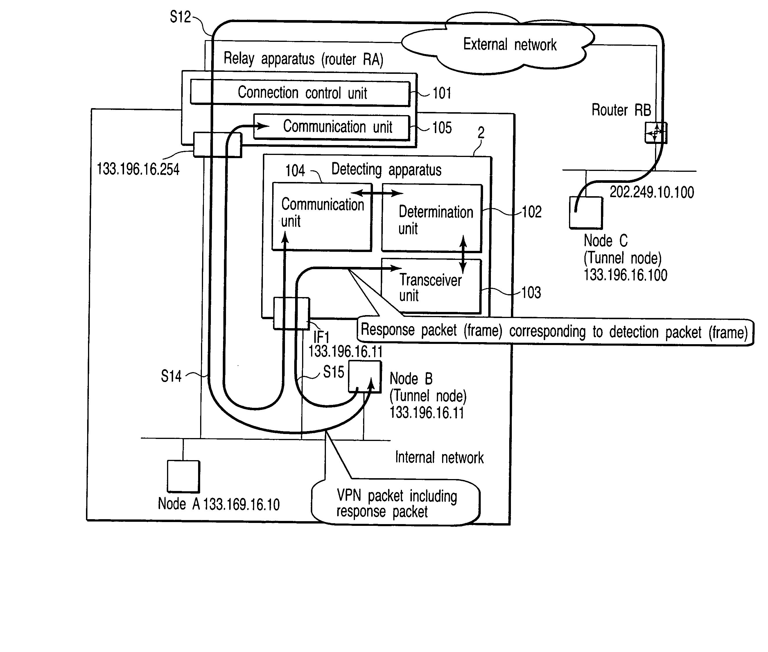
[0292] The second embodiment will exemplify a case wherein the function of the detecting apparatus 1 described above is divided into two parts, the detecting apparatus (a detecting apparatus 2 in this case) includes a determination unit 102 and a transceiver unit 103, and a connection control unit 101 comprises a relay apparatus such as a router RA connecting between an internal network and an external network.

1. Arrangements of Detecting Apparatus and Forwarding Apparatus

[0293]FIG. 32 shows examples of the arrangements of the detecting apparatus 2 and relay apparatus RA according to the second embodiment. The same reference numerals as in FIG. 32 denote the same parts in FIG. 6.

[0294] As in the first embodiment, the detecting apparatus includes the determination unit 102 and the transceiver unit 103, ...


PUM


Abstract

A VPN (Virtual Private Network) communication detecting apparatus connecting to an internal network for detecting a VPN node on an external network which connects to the internal network through a relay apparatus, transmits response request packet to test target node, receives response packet from the test target node in response to the response request packet, measures response time which is from first time point when the response request packet is transmitted to second time point when the response packet is received, and determines whether the test target node is the VPN node, based on correlation between the response time and delay time inserted by the relay apparatus when test target packet pass through the relay apparatus, the test target packet, if the test target node is the other of the VPN nodes, including the response request packet or the response packet.

Description

CROSS-REFERENCE TO RELATED APPLICATIONS [0001] This application is based upon and claims the benefit of priority from prior Japanese Patent Application No. 2006-068004, filed Mar. 13, 2006, the entire contents of which are incorporated herein by reference. BACKGROUND OF THE INVENTION [0002] 1. Field of the Invention [0003] The present invention relates to a Virtual Private Network (VPN) and, more particularly, to a method and apparatus for detecting a node on an external network which is performing VPN communication with a node on an internal network. [0004] 2. Description of the Related Art [0005] The forms of connecting basic networks in remote places include a technique called Virtual Private Network (VPN). [0006] Layer 3 VPN (L3VPN) is a technique of constructing a virtual network on a real network by performing “encapsulation”, i.e., storing an IP packet in an IP packet in the real network. This technique is sometimes called IP-VPN, Internet VPN, or the like. However, L3VPN, wh...

Claims


Application Information

Patent Timeline
IPC IPC(8): H04L12/28H04L12/66H04L12/70
CPCH04L12/4633H04L63/029H04L63/0272
Inventor MERA, KEISUKEESAKA, NAOKIMATSUZAWA, SHIGEO
Owner KK TOSHIBA
Why Eureka
Try Eureka