Developing apparatus

a technology of developing apparatus and development equipment, which is applied in the direction of electrographic process equipment, instruments, optics, etc., can solve the problems of affecting the development process, so as to reduce the load on the developer

Inactive Publication Date: 2007-12-06
CANON KK
View PDF26 Cites 10 Cited by
  • Summary
  • Abstract
  • Description
  • Claims
  • Application Information

AI Technical Summary

Benefits of technology

[0014] An object of the present invention is to provide a developing apparatus reducing a load onto a developer in a developing apparatus.

Problems solved by technology

When the above-mentioned developer supplying member or developer removing member is contacted with a developer carrying member, repeating multiple times an image forming operation leads to a larger load on a developer, thereby resulting in a further deterioration of a developer to cause the occurrence of a faulty image.
Moreover, on the other hand, since a magnetic force cannot be utilized in a developing apparatus using a nonmagnetic developer, the supply of a developer to the developer carrying member is insufficient.

Method used


Image

  • Developing apparatus
  • Developing apparatus
  • Developing apparatus

Examples


embodiment 1

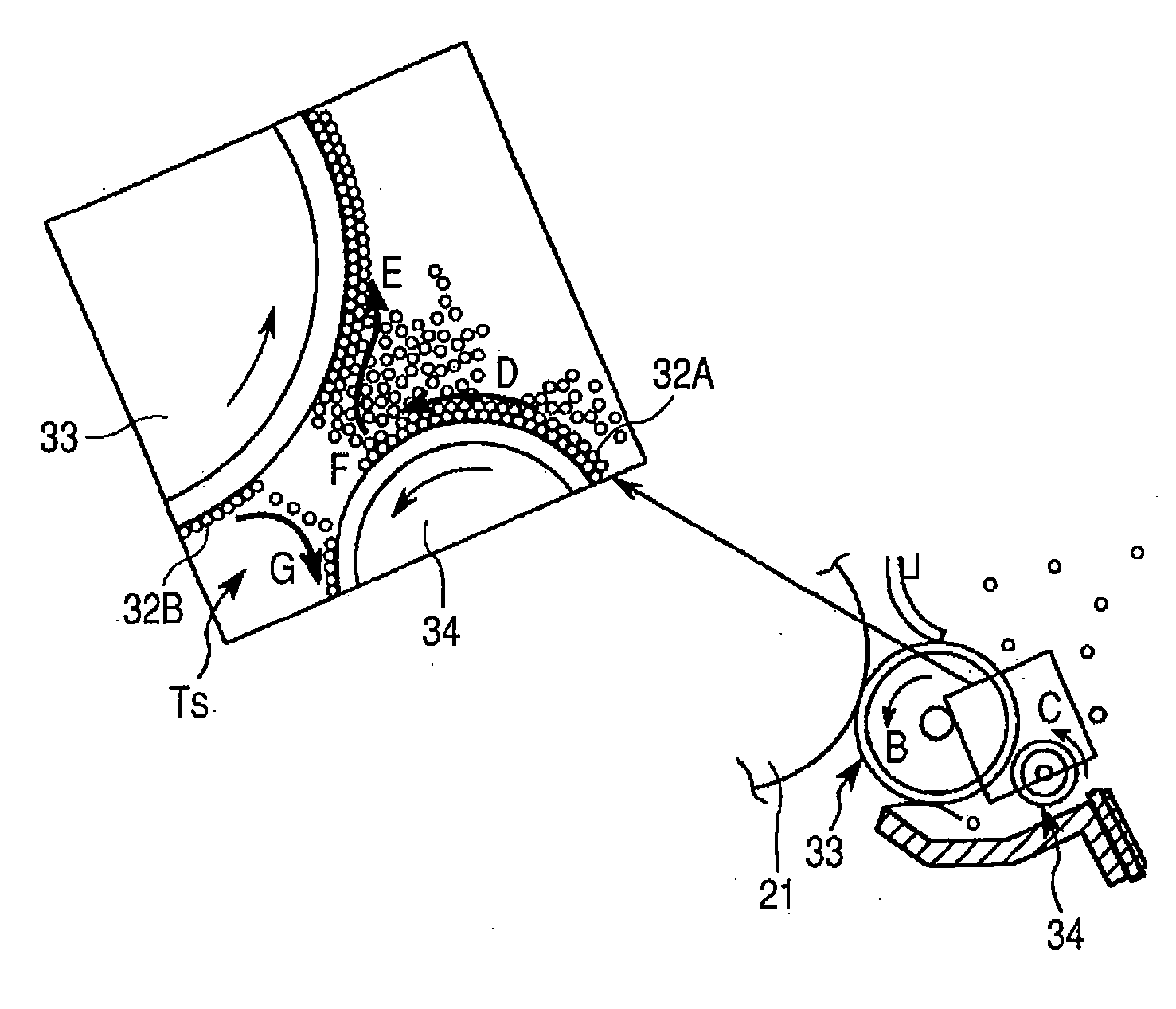
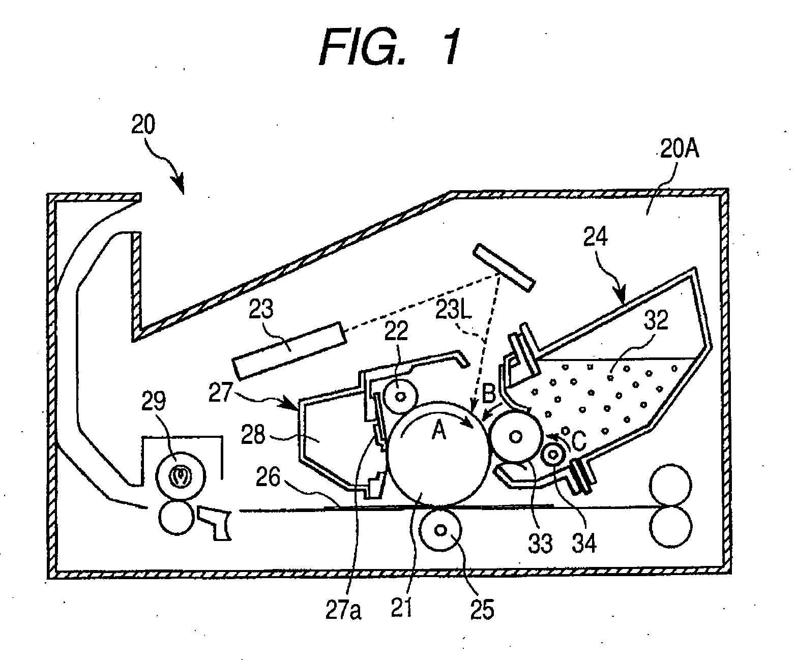
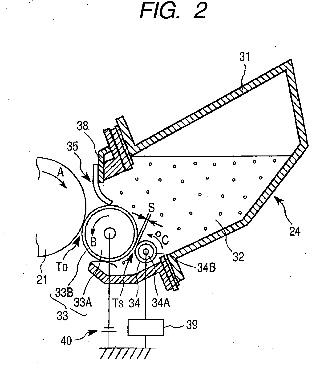
[0027]FIG. 1 is a schematically sectional view of an image forming apparatus to which a developing apparatus according to the present invention is applied. FIG. 2 is a schematically sectional view of the developing apparatus.

[0028] First, an image forming operation of the image forming apparatus according to this embodiment is described.

[0029] In this embodiment, an image forming apparatus 20 is provided with a drum-shaped electrophotographic photosensitive member as an image bearing member, which is a photosensitive drum 21. This photosensitive drum 21 is supported rotatably in the direction indicated by an arrow A. There are located at the peripheral portion of the photosensitive drum 21 a charger 22, an exposure device 23, and a developing apparatus 24.

[0030] First, the photosensitive drum 21 is uniformly charged with the charger 22, thereafter, in this embodiment, exposed with a laser beam 23L from a laser optical device, being the exposure device 23, and formed with an elect...

embodiment 2

[0104] In this embodiment, the specifications of an alternating current voltage to be applied to an insulator coated electrode roller is changed with respect to the embodiment 1, and the other construction is the same as that of the embodiment 1. Furthermore, in this embodiment, a direct potential to be applied to the electrode roller, with respect to a direct potential to be applied to the developing roller (−300 V), is set to be on the opposite side to the normal charging polarity of the toner. In this embodiment (experimental examples 15, 19 and 20), to the insulator coated electrode roller 34 illustrated in FIG. 2, a bias of an alternating current voltage of a rectangular wave of 3 kVpp and a frequency of 400 Hz being superimposed on a direct current voltage of +1.5 kV is applied from the power supply 39 of the image forming apparatus. In experimental examples 16, 17 and 18, being embodiments, a direct current voltage to be applied to the electrode roller and a peak-to-peak volt...

embodiment 3

[0112]FIG. 5 illustrates another embodiment of a developing apparatus according to the present invention. In this embodiment, a developing apparatus 50 can be applied to the image forming apparatus described in the embodiment 1, and the description of the image forming apparatus made in the embodiment 1 are incorporated in the embodiment 3. Also in the developing apparatus 50 according to this embodiment, the entire construction and function thereof are the same as those of the developing apparatus 24 of the embodiment 1 and the embodiment 2, so that like reference numerals denote members of the same construction and function, duplicated descriptions thereof are omitted, and mainly, characteristics of this embodiment will be described hereinafter.

[0113] In FIG. 5, the developing apparatus 50 according to this embodiment is provided with a developing container 51 in which a nonmagnetic toner 32 as a mono-component developer is contained, and a developing sleeve 52 as a developer car...


PUM


Abstract

A developing apparatus including: a developer carrying member carrying a developer with which an electrostatic image on an image bearing member is developed; a developer supplying/removing member having a conductive member and an insulating member on the surface thereof, and provided apart from the developer carrying member to supply and remove the developer to and from the developer carrying member, and moving directions of the developer carrying member and the developer supplying/removing member being opposed in a developer supplying position; and an electric field producing device producing between the developer carrying member and the developer supplying/removing member an oscillating electric field, in which direct potentials of the conductive member and the developer carrying member are the same, or the direct potential of the conductive member, with respect to the direct potential of the developer carrying member, is on the opposite side to a normal charging polarity of the developer.

Description

BACKGROUND OF THE INVENTION [0001] 1. Field of the Invention [0002] The present invention relates to a developing apparatuses for developing an electrostatic image formed on an image bearing member with a developer to be a visible image, which is a toner image. A developing apparatus can be used in e.g., electrophotographic image forming apparatuses, for example, copying machines, printers, or facsimile machines. [0003] 2. Description of the Related Art [0004] Some conventional developing apparatuses include a developer supplying member supplying a developer to a developer carrying member conveying a developer for causing an electrostatic latent image formed on an image bearing member to be visible. [0005] Furthermore, although after an electrostatic latent image is made visible, a developer remains on the developer carrying member as a history thereof, some conventional developing apparatuses include a developer removing member removing this remaining developer. [0006] When the abo...

Claims


Application Information

Patent Timeline
Patent Type & Authority Applications(United States)
IPC IPC(8): G03G15/08
CPCG03G15/0808G03G15/06
Inventor TAKASHIMA, KOICHIROISHII, YASUYUKIHIRATA, YUICHIROMATSUNAGA, TOMONORI
Owner CANON KK
Why Eureka
Try Eureka