Devices and Methods for Positioning Dried Reagent In Microfluidic Devices
a microfluidic device and reagent technology, applied in the field of microfluidic devices and methods, can solve the problems of affecting the performance of the device, affecting the reaction efficiency between samples, and insufficient filling of the device portion,
- Summary
- Abstract
- Description
- Claims
- Application Information
AI Technical Summary
Benefits of technology
Problems solved by technology
Method used
Image
Examples
example 1
Filling of Chambers Having Centered Dried Reagent
[0115]135 nL of liquid reagent was dispensed at the center of the sample chambers of microfluidic chips by a liquid reagent dispenser and then dried (e.g., lyophilized). FIG. 10A is a photograph of a portion of a microfluidic chip 110 showing a plurality of chambers 120 having the dried reagent R (indicated by the white spots) positioned in the center of the chambers. As mentioned above, the 20 chambers shown in FIG. 10A were the chambers used in the calculation of the filling efficiency. The chips containing the centered dried reagent, as depicted in FIG. 1A, were then laminated as described above. The chips 110 also included a hydrophobic membrane 135 for ventilation (shown via the white strip in FIG. 10A), as described above. The main fluid channel 126 was connected to a syringe pump at a left-hand, top side of the channel 126 in FIG. 10A via an inlet (not shown) and the chambers 120 were filled via the main fluid channel 126 and i...
example 2
Filling of Chambers Having Dried Reagent Positioned at an Inlet Side
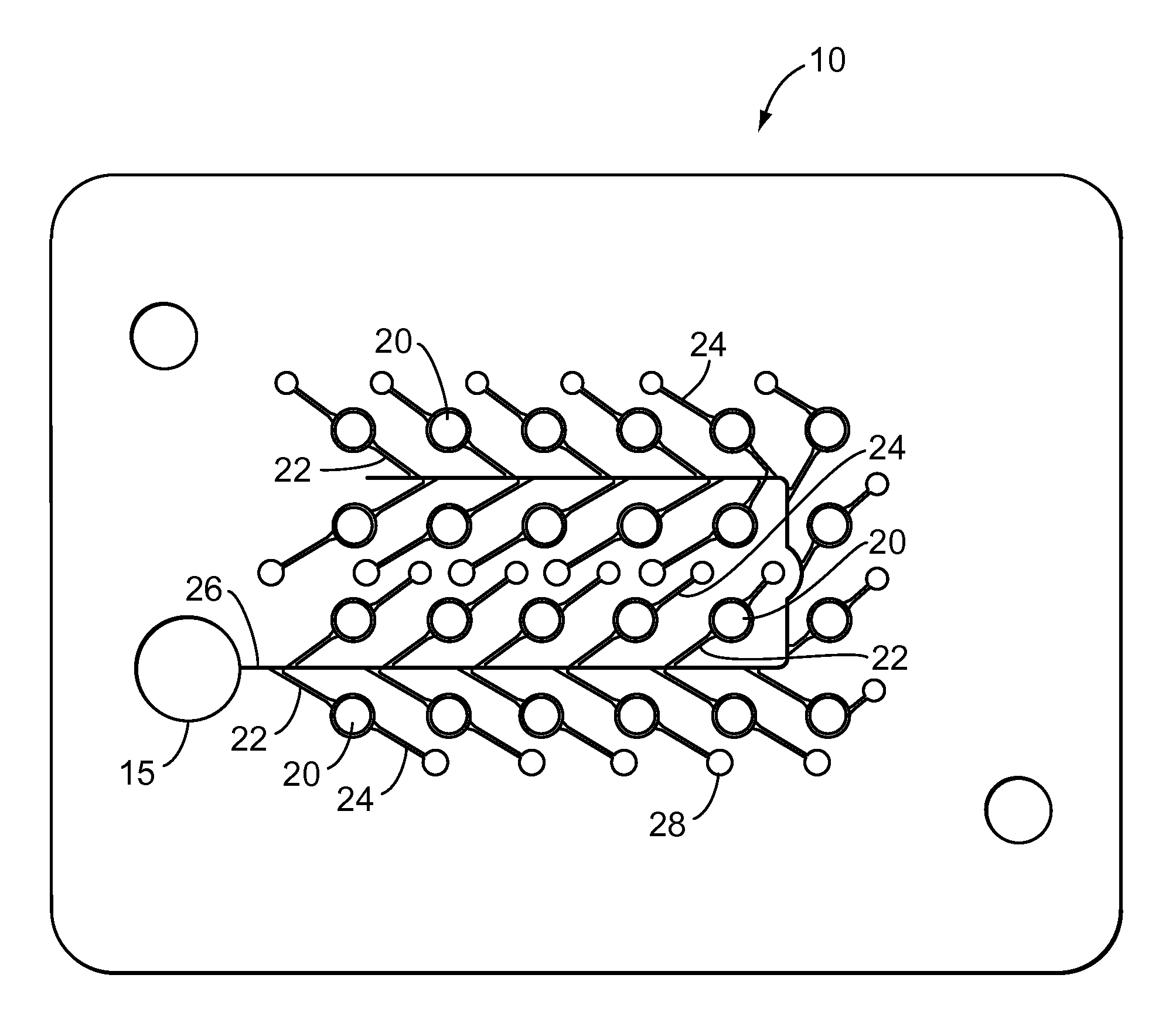
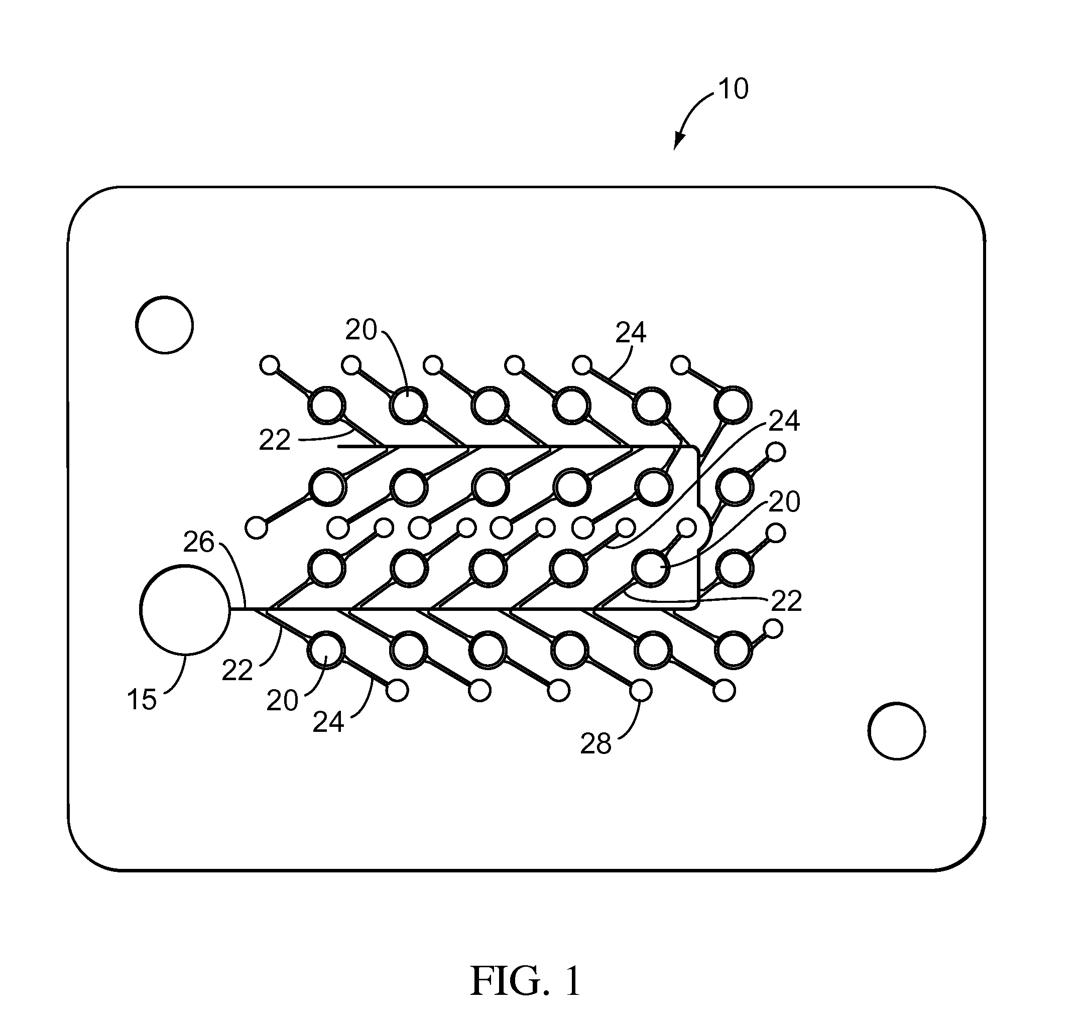
[0118]135 nL of liquid reagent was dispensed toward an inlet side (e.g., proximate the inlet channel) of all but two of the chambers of microfluidic chips by a liquid reagent dispenser and then dried (i.e., lyophilized). The two chambers in which reagent was positioned toward an outlet side were chambers positioned in the farthest column to the right from the fluid inlet (as shown in FIG. 1 and not shown in FIGS. 12A and 12B) and the four chambers in that column were excluded from calculating the filling efficiency. FIG. 12A is a photograph of a portion of a microfluidic chip 210 showing a plurality of chambers 220 having the dried reagent R (indicated by the white spots) positioned at an inlet side of the chambers 220 proximate the inlet channel 222 of the chambers 220. The 20 chambers shown in FIG. 12A were the chambers used in the calculation of the filling efficiency. The chips containing the inlet side dried re...
example 3
Filling of Chambers Having Dried Reagent Positioned at an Inlet Side
[0123]In an attempt to increase the filling efficiency of chambers containing inlet side dried reagent, tests were performed using a higher volume of liquid reagent dispensed on the inlet side of the chambers of microfluidic chips. In these tests, 260 nL of liquid reagent was dispensed toward an inlet side (e.g., proximate the inlet channel) of all but two of the chambers of microfluidic chips by a liquid reagent dispenser and then dried (i.e., lyophilized). The two chambers in which reagent was positioned toward an outlet side were chambers positioned in the farthest column to the right from the fluid inlet (as shown in FIG. 1 and not shown in FIGS. 14A and 14B) and the four chambers in that column were excluded from calculating filling efficiency. FIG. 14A is a photograph of a portion of a microfluidic chip 410 showing a plurality of chambers 420 having the dried reagent R (indicated by the white spots) positioned...
PUM
| Property | Measurement | Unit |
|---|---|---|
| diameter | aaaaa | aaaaa |
| depth | aaaaa | aaaaa |
| diameter | aaaaa | aaaaa |
Abstract
Description
Claims
Application Information
 - R&D
- Intellectual Property
- Life Sciences
- Materials
- Tech Scout
- Unparalleled Data Quality
- Higher Quality Content
- 60% Fewer Hallucinations
Browse by: Latest US Patents, China's latest patents, Technical Efficacy Thesaurus, Application Domain, Technology Topic, Popular Technical Reports.
© 2025 PatSnap. All rights reserved.Legal|Privacy policy|Modern Slavery Act Transparency Statement|Sitemap|About US| Contact US: help@patsnap.com


