System and method for 3D frequency domain waveform inversion based on 3D time-domain forward modeling

Active Publication Date: 2007-12-06
BP CORP NORTH AMERICA INC
View PDF8 Cites 63 Cited by
  • Summary
  • Abstract
  • Description
  • Claims
  • Application Information

AI Technical Summary

Benefits of technology

[0023] By way of summary, the instant invention makes practical for the first time a full 3D implementation of frequency-domain waveform inversion through the use of time-domain finite-difference forwar

Problems solved by technology

Broadly speaking, the “inverse problem” attempts to estimate physical properties of the Earth from the recorded seismic data.
However, because of the computational diffi

Method used


Image

  • System and method for 3D frequency domain waveform inversion based on 3D time-domain forward modeling
  • System and method for 3D frequency domain waveform inversion based on 3D time-domain forward modeling
  • System and method for 3D frequency domain waveform inversion based on 3D time-domain forward modeling

Examples


Embodiment Construction

[0037] While this invention is susceptible of embodiment in many different forms, there is shown in the drawings, and will herein be described hereinafter in detail, some specific embodiments of the instant invention. It should be understood, however, that the present disclosure is to be considered an exemplification of the principles of the invention and is not intended to limit the invention to the specific embodiments or algorithms so described.

General Environment of the Invention

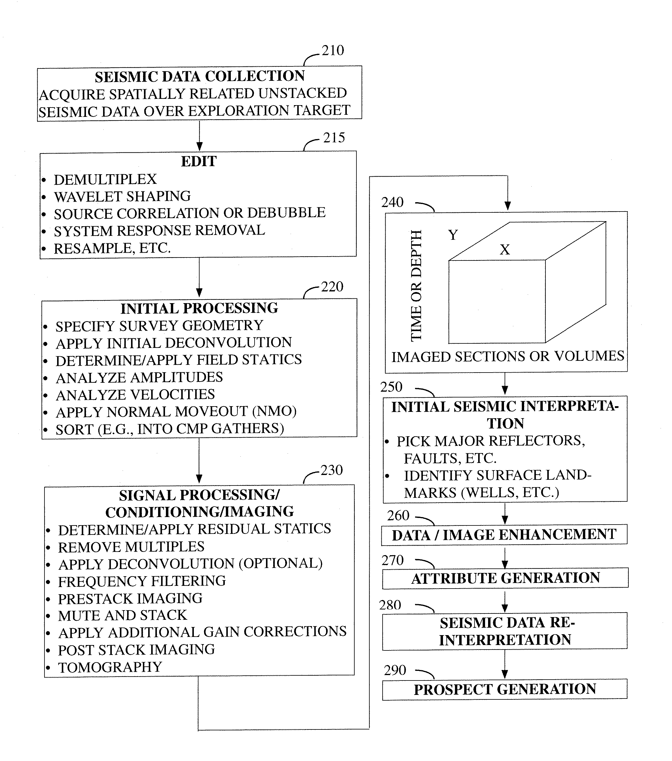
[0038]FIG. 1 illustrates the general environment in which the instant invention would typically be used. As a preliminary step 110, it is customary to undertake at least some basic planning of a seismic survey in advance of conducting it. In addition to determining the location of the survey on the surface of the earth, typically survey-related parameters such as the trace / shot spacing, sample rate, number of recording channels, etc., will also be specified in advance of conducting the survey. Seismic ...


PUM


Abstract

According to a first preferred aspect of the instant invention, there is provided an efficient method of computing a 3D frequency domain waveform inversion based on 3D time domain modeling. In the preferred arrangement, 3D frequency domain wavefields are computed using 3D time-domain modeling and a discrete Fourier transformation that is preferably computed “on the fly” instead of solving the large systems of linear equations that have traditionally been required by direct frequency domain modeling. The instant invention makes use of the theory of gradient-based waveform inversion that estimates model parameters (for example velocities) by matching modeled data to field data sets. Preferably the modeled data are calculated using a forward modeling algorithm.

Description

RELATED CASE [0001] This application claims the benefit of U.S. Provisional Patent Application Ser. No. 60 / 809,507 filed on May 31, 2006, and incorporates said provisional application by reference into this disclosure as if fully set out at this point.TECHNICAL FIELD [0002] This invention relates to the general subject of seismic exploration and, in particular, to methods for quantifying and visualizing complex subsurface structures with seismic data. BACKGROUND OF THE INVENTION [0003] A seismic survey represents an attempt to image or map the subsurface of the earth by sending sound energy down into the ground and recording the “echoes” that return from the rock layers below. The source of the down-going sound energy might come, for example, from explosions or seismic vibrators on land, or air guns in marine environments. During a seismic survey, the energy source is positioned at various locations near the surface of the earth above a geologic structure of interest. Each time the ...

Claims


Application Information

Patent Timeline
IPC IPC(8): G01V1/00G01V1/28G06F19/00
CPCG01V1/28G01V2210/67G01V3/083
Inventor SIRGUE, LAURENTETGEN, JOHN T.ALBERTIN, UWEBRANDSBERG-DAHL, SVERRE
Owner BP CORP NORTH AMERICA INC
Why Eureka
Try Eureka