Draining liquid from a steam generator of a fabric treatment appliance

a fabric treatment and steam generator technology, applied in the direction of cleaning using liquids, textiles and papermaking machines, other washing machines, etc., can solve the problems of detrimental to heat transfer and fluid flow, and scale and sludge formation in the steam generation chamber

Inactive Publication Date: 2007-12-13
WHIRLPOOL CORP
View PDF99 Cites 52 Cited by
  • Summary
  • Abstract
  • Description
  • Claims
  • Application Information

AI Technical Summary

Benefits of technology

[0015]The drain can fluidly couple the chamber to a sump portion of the tub and can bypass the drum.

Problems solved by technology

A common problem associated with steam generators involves the formation of scale and sludge within the steam generation chamber.
Water from a household water supply typically contains dissolved substances, such as calcium and magnesium, which lead to the formation of scale and sludge in the steam generation chamber when the water is heated.
Formation of scale and sludge can detrimentally affect heat transfer and fluid flow and can lead to premature failure of the heater.

Method used


Image

  • Draining liquid from a steam generator of a fabric treatment appliance
  • Draining liquid from a steam generator of a fabric treatment appliance
  • Draining liquid from a steam generator of a fabric treatment appliance

Examples


first embodiment

[0067]The first valve 90 has a corresponding first flow rate, while the second valve 92 has a corresponding second flow rate different than the first flow rate. The flow rates can be selected based on a desired flow rate for different steps of the method 100. For example, the first valve 90 can be used for the steam generation step 102 when a relatively low flow rate is desired, while the second valve 92 can be used during the steam generator cleaning step 104 when a relatively high flow rate is desired, such as for the flushing of the steam generation chamber 74A. Using a relatively high flow rate during the steam generator cleaning step 104 can contribute to a more effective cleaning of the steam generation chamber 74A. As the flow rate increases, erosion of scale from the inside surface 72A of the steam generation chamber 74A can increase. As examples, the first flow rate can be about 0.25 liters per minute (LPM), and the second flow rate can be about 10 LPM. Similar to the secon...

third embodiment

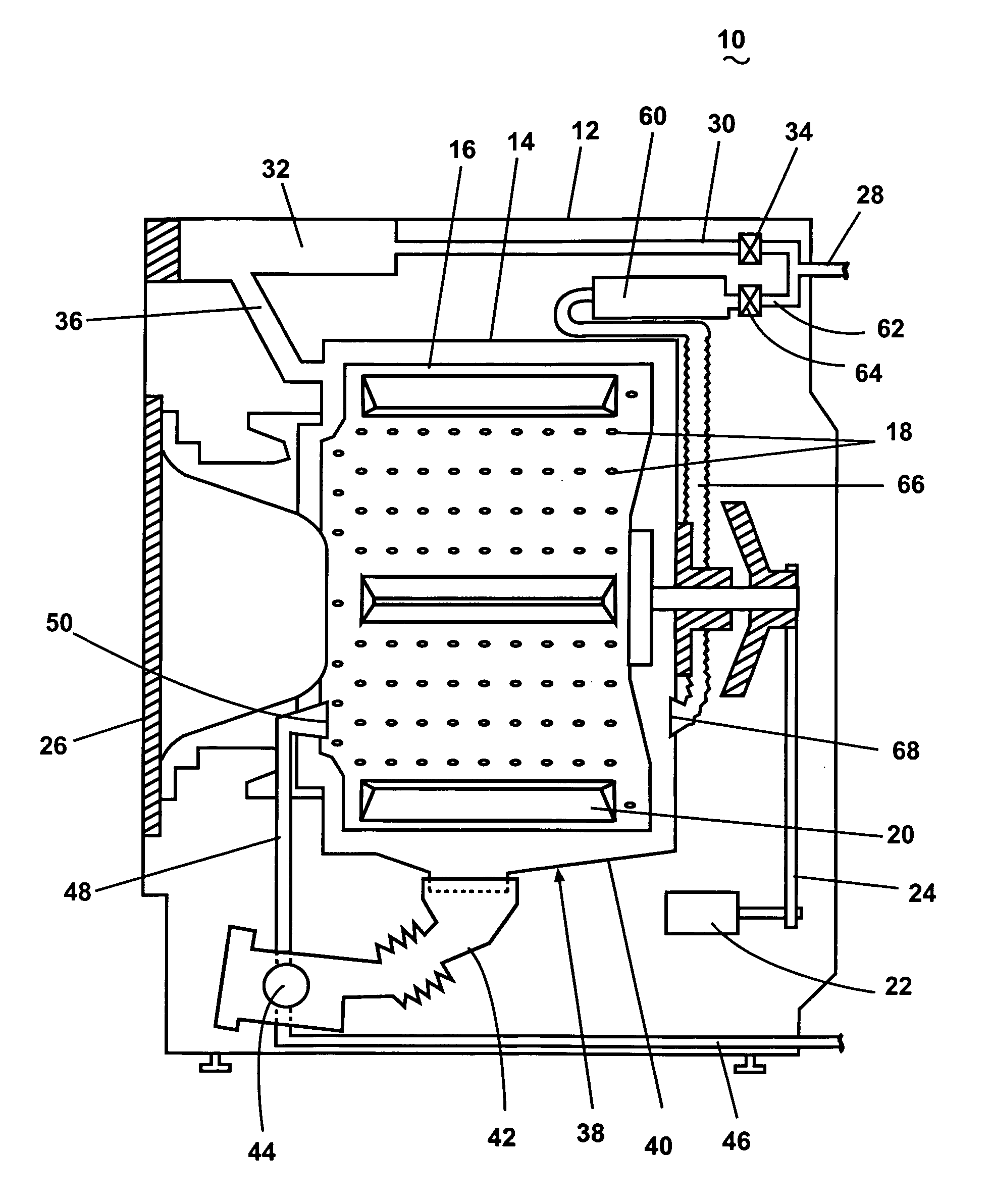
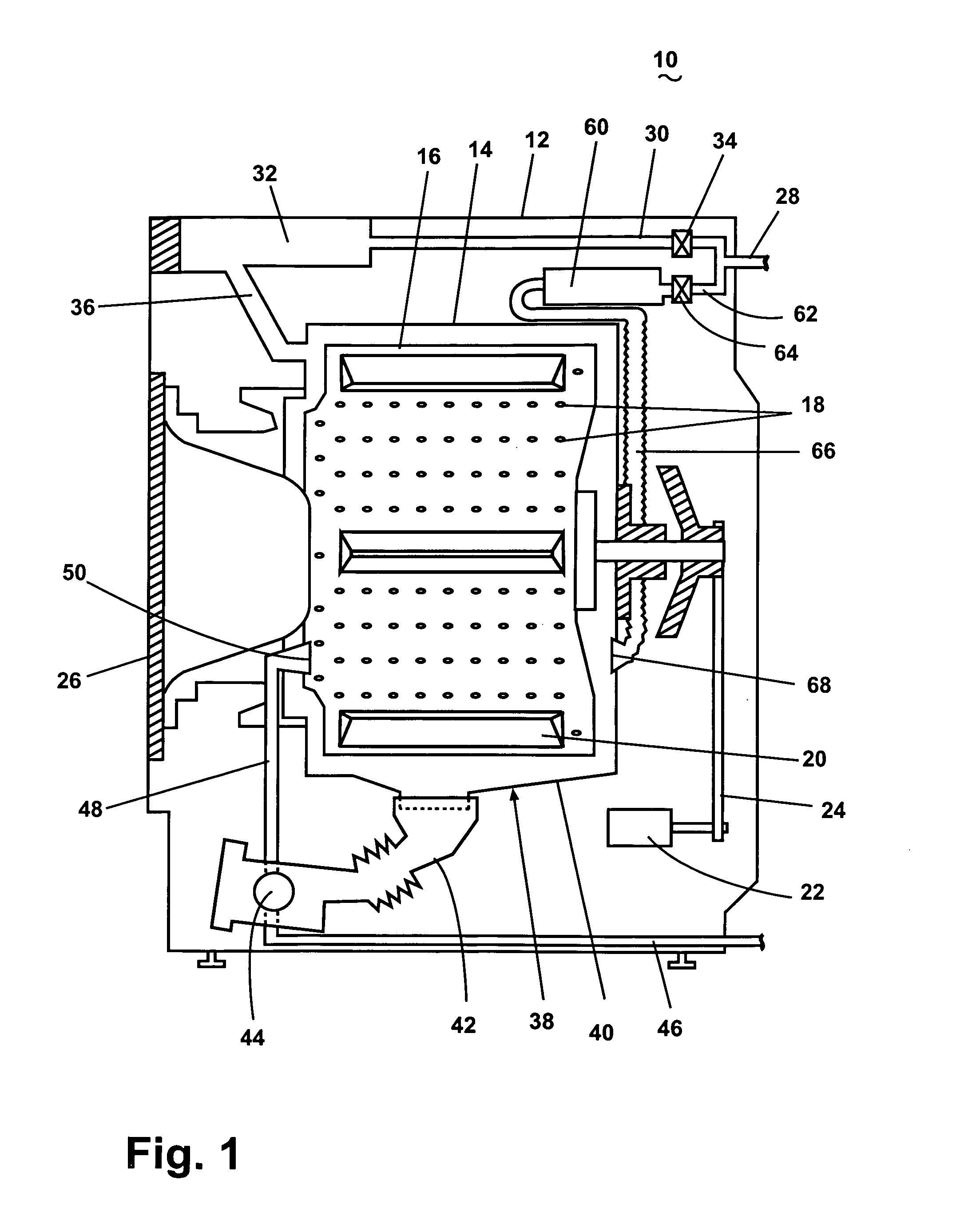
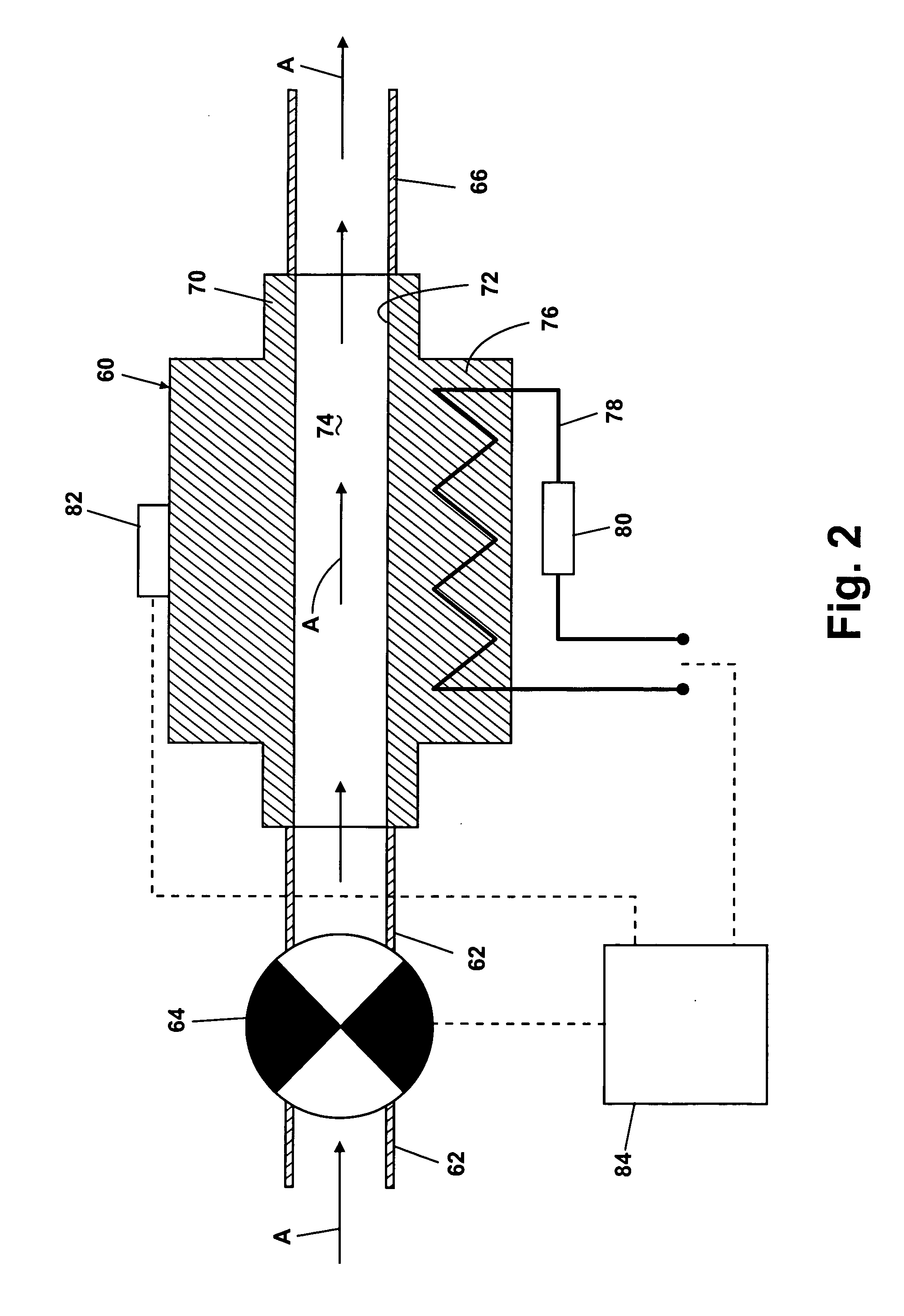
[0068]FIG. 9 illustrates the washing machine 10 with a third embodiment steam generator 60B, which is shown in detail in FIG. 10, that can be used to execute the method 100. FIG. 9 is a schematic diagram and only shows the cabinet 12, the tub 14, the drum 16, the steam generator 60B, and fluid / steam conduits for the steam generator 60B. The fluid / steam conduits comprise a water supply line 170 that couples a household water supply 172 with the steam generator 60B, a water outlet line 174 that fluidly couples the steam generator 60B with the drum 16 for transporting water from the steam generator 60B to the drum 16, a steam outlet line 176 that fluidly couples the steam generator 60B with the drum 16 for transporting steam from the steam generator 60B to the drum 16, and a drain conduit 178 that fluidly couples the steam generator 60B with the tub 14. A supply valve 180 in the water supply line 170 controls the flow of fluid through the water supply line 170 to the steam generator 60...


PUM


Abstract

A method of operating a fabric treatment appliance comprises a steam generation step and, after the completion of the steam generation step, a draining step comprising draining liquid remaining in a chamber of the steam generator to a tub of the fabric treatment appliance. The steam generator in one embodiment can comprise the chamber, an inlet configured to introduce liquid into the chamber, an outlet configured to exhaust steam from the chamber, and a drain coupling the chamber to the tub and configured to drain liquid from the chamber to the tub.

Description

BACKGROUND OF THE INVENTION[0001]1. Field of the Invention[0002]The invention relates to draining liquid from a steam generator of a fabric treatment appliance.[0003]2. Description of the Related Art[0004]Some fabric treatment appliances, such as a washing machine, a clothes dryer, and a fabric refreshing or revitalizing machine, utilize steam generators for various reasons. The steam from the steam generator can be used to, for example, heat water, heat a load of fabric items and any water absorbed by the fabric items, dewrinkle fabric items, remove odors from fabric items, etc.[0005]A common problem associated with steam generators involves the formation of scale and sludge within the steam generation chamber. Water from a household water supply typically contains dissolved substances, such as calcium and magnesium, which lead to the formation of scale and sludge in the steam generation chamber when the water is heated. Scale and sludge are, respectively, hard and soft deposits; t...

Claims


Application Information

Patent Timeline
Patent Type & Authority Applications(United States)
IPC IPC(8): B08B3/12D06F35/00D06F37/00D06B19/00
CPCD06F39/083D06F39/008
Inventor WONG, NYIK SIONGVAIDHYANATHAN, RAVEENDRANHARDAWAY, ANTHONY H.LUCKMAN, JOEL A.
Owner WHIRLPOOL CORP
Why Eureka
Try Eureka