Transmission lock

a technology for transmission locks and locking devices, applied in mechanical control devices, differential gearings, limiting/preventing/returning movement of parts, etc., can solve problems such as safety problems, and achieve the effect of preventing the actuation of the blocking devi

Inactive Publication Date: 2007-12-13
GETRAG GETRIEBE & ZAHNRADFABRIK HERMANN HAGENMEYER GMBH & CO KG
View PDF5 Cites 62 Cited by
  • Summary
  • Abstract
  • Description
  • Claims
  • Application Information

AI Technical Summary

Benefits of technology

[0036] Furthermore, it is advantageous if a first position sensor is provided, which detects whether the lock arrangement is in the locking position or in the release position.
[0037] By means of the position sensor, in a control device, a decision as to whether the

Problems solved by technology

Particularly when the motor vehicle is stopped on a gradient, this may present safety p

Method used


Image

  • Transmission lock
  • Transmission lock
  • Transmission lock

Examples


Embodiment Construction

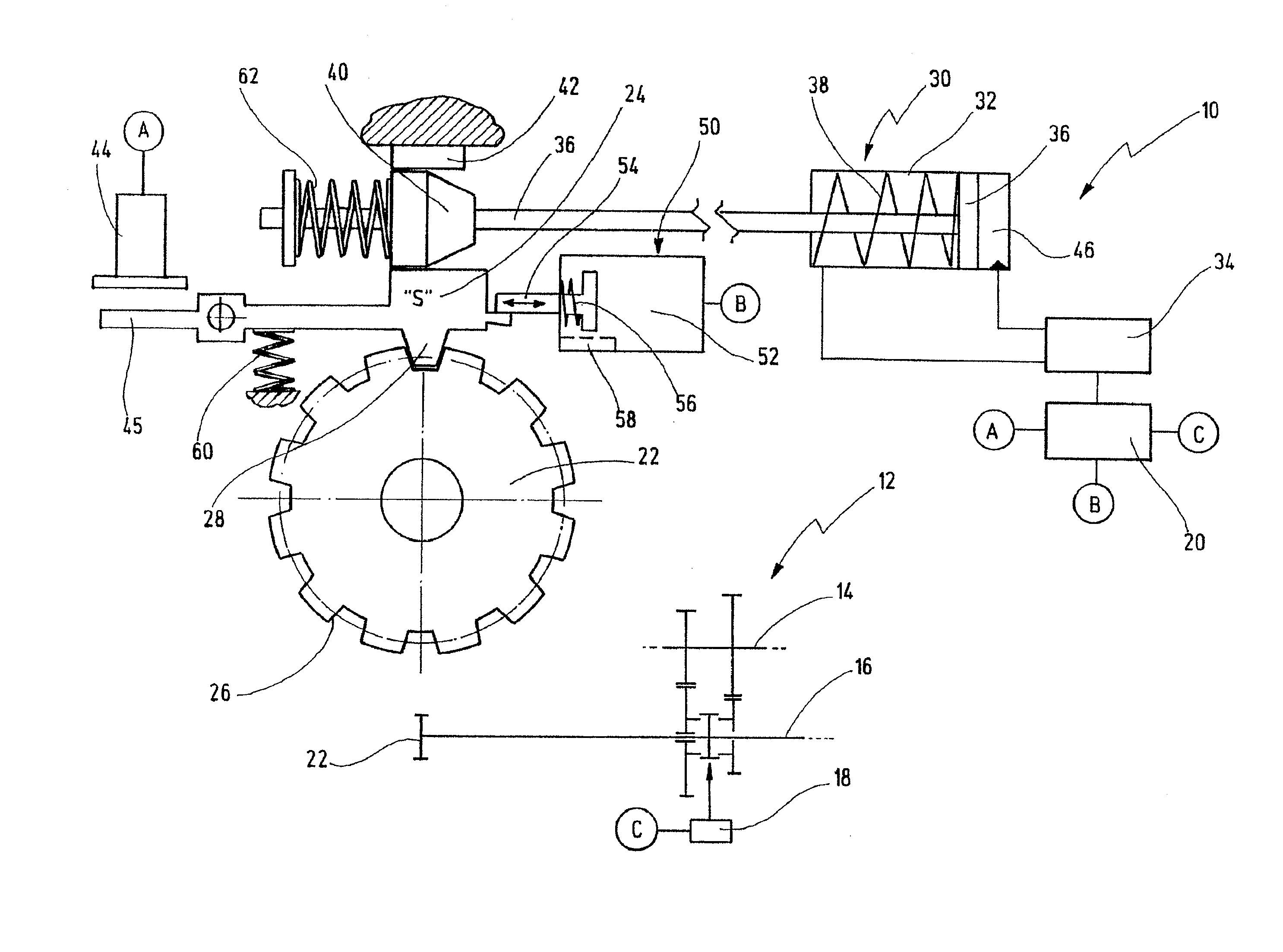
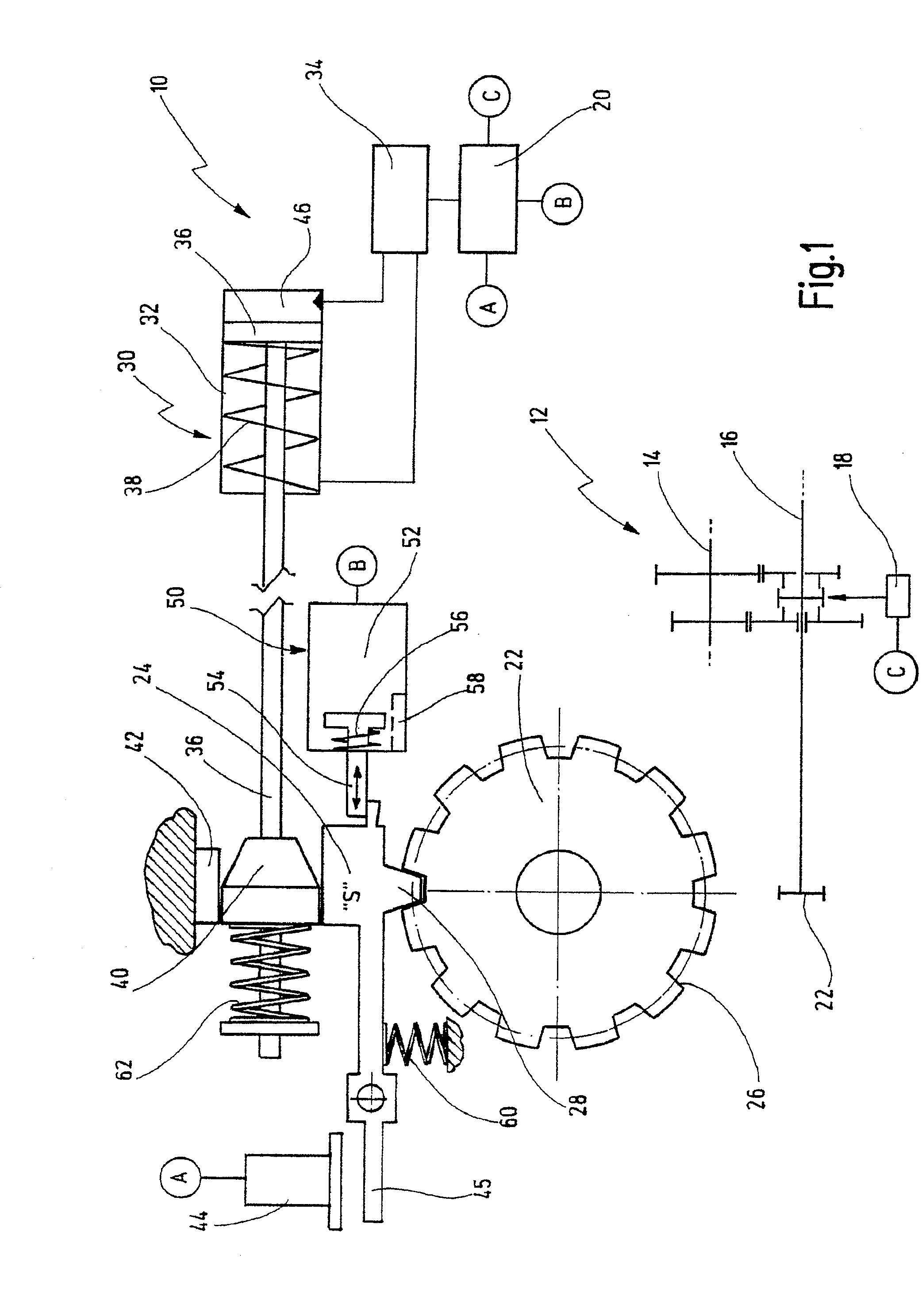
[0057] A first embodiment of a parking-lock arrangement according to the invention is designated in general by 10 in FIG. 1.

[0058] The lock arrangement 10 is designed as a parking-lock arrangement for an automated transmission 12. The automated transmission 12, in the case illustrated, is designed, for example, as a countershaft transmission, by means of which, for example, two or more wheel sets can be shifted alternately into the force flux by means of respective shift-clutch assemblies.

[0059] The transmission has an input shaft 14 and an output shaft 16. The input shaft 14 is connected, for example via a starting clutch or a double-clutch assembly, to an engine, such as an internal combustion engine. The output shaft 16, as a rule, is connected positively to driving wheels of the motor vehicle and constitutes a power take-off.

[0060] A shift-clutch assembly can be actuated in. each case by means of a shift actuator 18. The shift actuator 18 is connected to an overriding control...


PUM


Abstract

A lock arrangement for a transmission, in particular in the form of a parking-lock arrangement for an automated transmission. The lock arrangement is prestressed by a first spring accumulator into a locking position in which the transmission is locked. The lock arrangement is capable of being shifted by means of an actuator from the locking position into a release position in which the transmission is released. The lock arrangement has an electronically activatable blocking device which is designed for blocking the lock arrangement mechanically in the locking position.

Description

BACKGROUND OF THE INVENTION [0001] The present invention relates to a lock arrangement for a transmission, in particular a parking-lock arrangement for an automated transmission, the lock arrangement being prestressed by a first spring accumulator into a locking position in which the transmission is locked, and the lock arrangement being capable of being shifted by means of an actuator from the locking position into a release position in which the transmission is unlocked. [0002] Parking-lock arrangements of this type are known for automatic transmissions, including automatic converters, automated shift transmissions, double clutch transmissions, etc. [0003] The present invention relates, furthermore, to a method for activating such a lock arrangement. [0004] DE 41 27 991 C2 discloses a parking lock for an automatic transmission, with a spring accumulator which generally presses the parking lock into the locking position, and with an electrohydraulic actuator, by means of which the ...

Claims


Application Information

Patent Timeline
IPC IPC(8): B60R25/06F16D65/28F16H48/22
CPCF16H48/22F16H63/3433Y10T74/19251F16H63/483Y10T74/20116F16H63/3483Y10T70/5925
Inventor SCHWEIHER, MARKHERDLE, LOTHARFLAIG, ARMIN
Owner GETRAG GETRIEBE & ZAHNRADFABRIK HERMANN HAGENMEYER GMBH & CO KG
Why Eureka
Try Eureka