Energy converting system

a technology of energy conversion and energy, applied in the field of electromagnetic systems, can solve the problems of difficult to generate reliable high-speed motion of such vehicles, the object made to travel at high-speed can lose stability and leave the track, and the need for much more power to achieve motion, etc., to achieve the effect of increasing system efficiency

Inactive Publication Date: 2007-12-13
INDAL DESIGN LAB
View PDF18 Cites 44 Cited by
  • Summary
  • Abstract
  • Description
  • Claims
  • Application Information

AI Technical Summary

Benefits of technology

[0021]To further increase the system efficiency the pick-up coil i

Problems solved by technology

The main problem of all such known systems is that it is difficult to generate reliable high speed motion of such vehicles because of the absence of attraction between the vehicle and the track, especially at higher speed on turns, and also when the track follows a vertical or nearly vertical path as in a vertical ring or spiral.
Even when track sections are configured horizontally an object made to travel at high speed can lose stability and depart the track due to centrifugal and other forces.
But these means in known systems also add resistance to motion, or drag

Method used


Image

  • Energy converting system
  • Energy converting system
  • Energy converting system

Examples


Embodiment Construction

[0034]The present invention will be described in detail below with reference to the accompanying drawings.

[0035]FIGS. 1-6A show embodiments of the present invention.

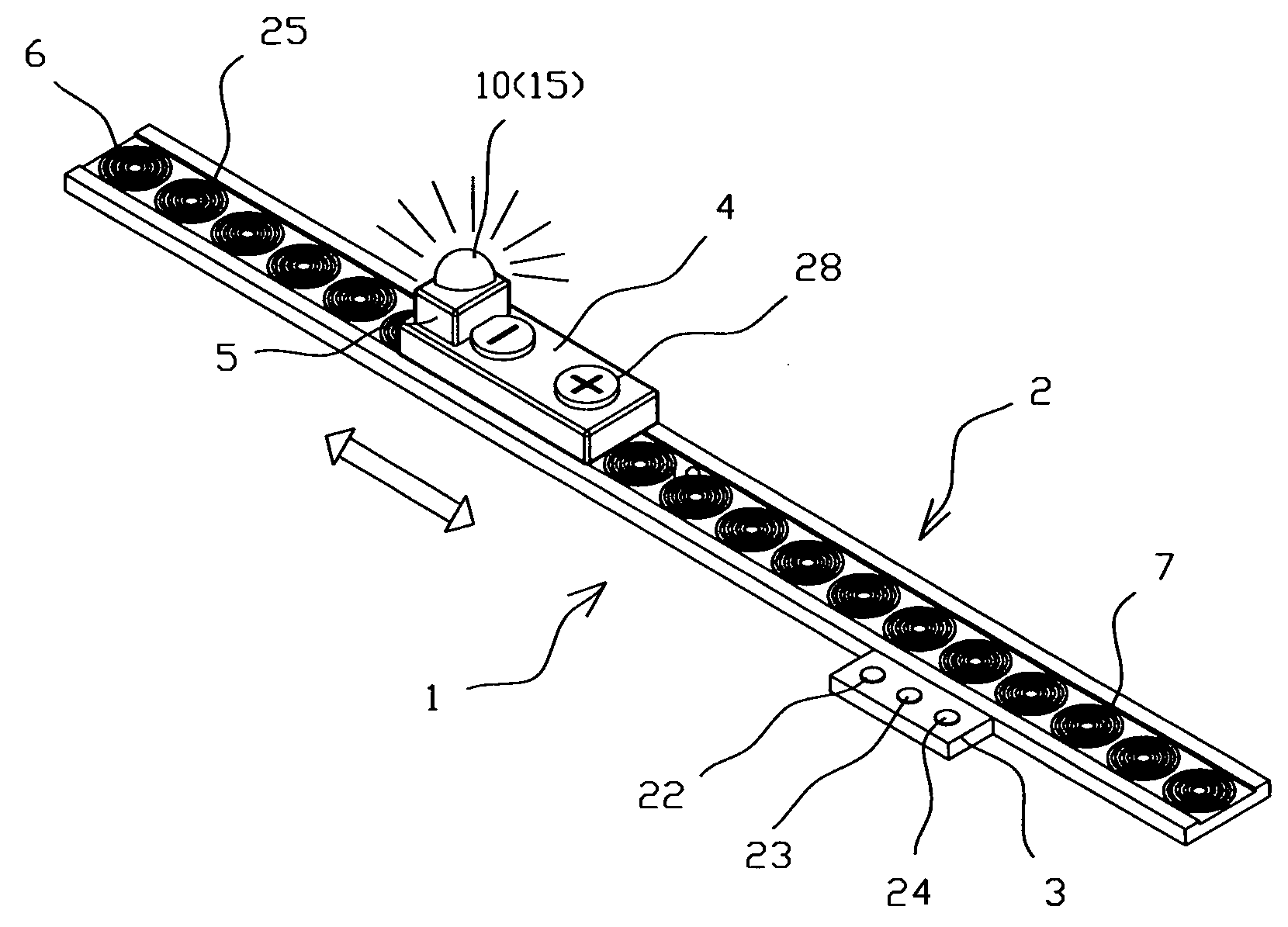
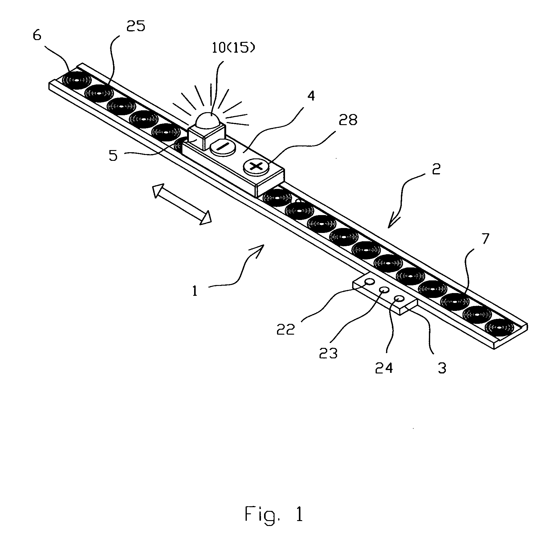
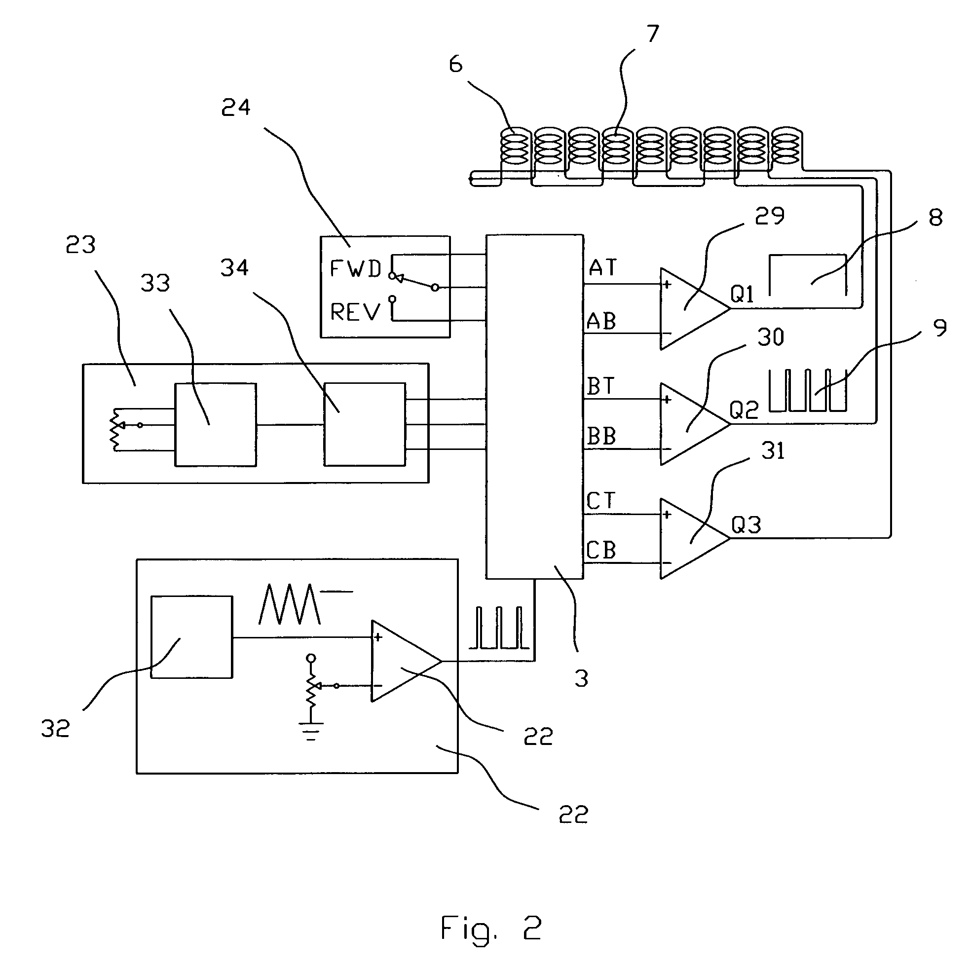
[0036]The energy converting system 1 according to the preferred embodiment (FIGS. 1-2) is comprised of a track 2, a controller 3, and at least one magnetized body 4 located on the track 2 and including an energy converting unit 5. The track 2 comprises electrically connected coil windings 6 spaced apart in a series way along the track 2 to form a multi-phase linear stator 7. The controller 3 is electrically connected with the linear stator 7 and generates a combination waveform consisting of a multi-phase propulsion signal 8 and a power signal 9. The stator 7 is executed as at least a 3-phase multi-phase linear stator. The propulsion and power signals 8 and 9 are distant by the corresponding frequencies of the signals. The propulsion signal 8 causes the interaction of the magnetized body 4 with the linear stator 7, thus ...


PUM


Abstract

An energy converting system is comprised of a track, a controller, and a magnetized body located on the track and including an energy converting unit. The track comprises electrically connected coil windings spaced apart in a series way along the track to form a 3-phase linear stator. The controller is electrically connected with the linear stator and generates a combination waveform consisting of a multi-phase propulsion signal and a power signal. The propulsion and power signals are at different frequencies. The propulsion signal causes the interaction of the magnetized body with the linear stator, thus propelling the magnetized body along the track. The energy converting unit comprises electrically connected energy consuming means and at least one pick-up coil inductively coupled to the linear stator, thus providing power to the energy consuming means.

Description

CROSS REFERENCE TO RELATED APPLICATIONS[0001]The present application claims the benefit of priority of U.S. Provisional Patent Application No. 60 / 801,253 filed May 18, 2006 for Edward Lopatinsky et al. the entire content of which is incorporated herein by reference.FIELD OF THE INVENTION[0002]The present invention relates generally to electromagnetic systems for moving mechanical bodies along predefined paths. More particularly, the present invention relates to toy and / or entertainment systems, and all subsystems in which it is useful to controllably move such a body upon such predefined paths and simultaneously transfer some energy from the path to the body. The present invention is particularly, but not exclusively, useful for systems that relate to toy motion devices such as vehicles.BACKGROUND OF THE INVENTION[0003]There are numerous designs of electromagnetic motion control systems executed as miniature toy railways that include a track and at least one vehicle located on said ...

Claims


Application Information

Patent Timeline
IPC IPC(8): B60L13/06
CPCA63H18/08A63H18/12A63H21/00B60L2200/26B60L5/005B60L13/04A63H33/26
Inventor LOPATINSKY, EDWARDFEDOSEYEV, LEVSCHAEFER, DANIELEISENSON, HENRY
Owner INDAL DESIGN LAB
Why Eureka
Try Eureka