Two-wavelength image sensor picking up both visible and infrared images

a technology of infrared and visible images, applied in the field of 2wavelength image sensors, can solve the problems of increased system size and production cost, disadvantageous resolution of visible image and thermal image, and large system size, and achieve the effect of eliminating the necessity of cooling, high resolution and high sensitivity

Active Publication Date: 2007-12-13
MITSUBISHI ELECTRIC CORP
View PDF6 Cites 38 Cited by
  • Summary
  • Abstract
  • Description
  • Claims
  • Application Information

AI Technical Summary

Benefits of technology

[0010]The present invention mainly contemplates a 2-wavelength image sensor that can obtain a visible image high in resolution and an infrared image high i

Problems solved by technology

However, such a system is large in size and requires a complicated image process between two types of optical images to analyze data.
The image sensor disclosed in Japanese Patent Laying-open No. 11-289492, however, detects visible ra

Method used


Image

  • Two-wavelength image sensor picking up both visible and infrared images
  • Two-wavelength image sensor picking up both visible and infrared images
  • Two-wavelength image sensor picking up both visible and infrared images

Examples


first embodiment

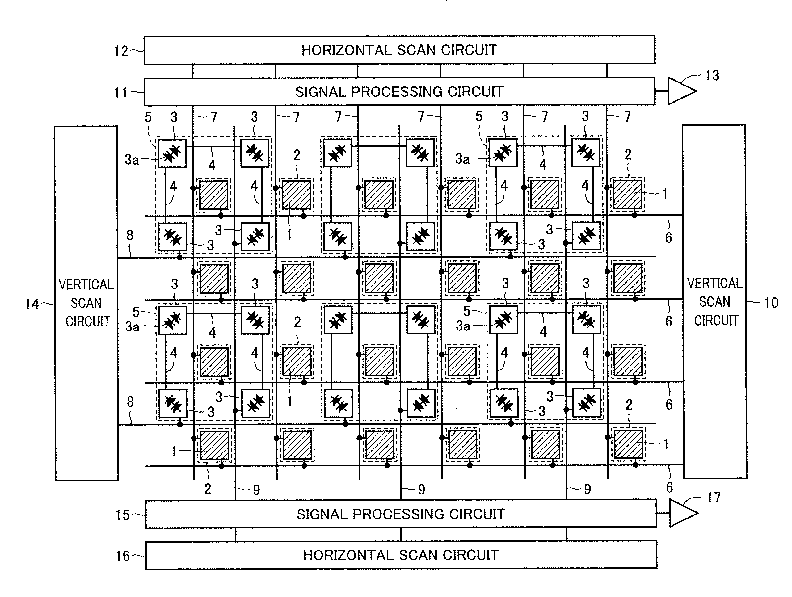
[0023]FIG. 1 is a plan view in configuration of the 2-wavelength image sensor of the present invention in a first embodiment. As shown in FIG. 1, the 2-wavelength image sensor includes a detector array including a plurality of visible radiation detectors I and a plurality of uncooled infrared radiation detectors 3. While in reality a large number of detectors 1 and 3 are provided, FIG. 1 shows 24 detectors for each type of detector for simplicity. Twenty four visible radiation detectors 1 and 24 uncooled infrared radiation detectors 3 are uniformly dispersedly arranged. More specifically, 24 visible radiation detectors 1 are arranged in four rows and six columns with a predetermined pitch and so are 24 uncooled infrared radiation detectors 3, and visible radiation detectors 1 and uncooled infrared radiation detectors 3 are displaced by a half pitch in the direction of the rows and that of the columns.

[0024]Visible radiation detector 1 is implemented by a Si pn junction photodiode an...

second embodiment

[0041]FIG. 5 is a plan view of a main portion of the present 2-wavelength image sensor in a second embodiment in comparison with FIG. 3, and FIG. 6 is a cross section in configuration of two adjacent infrared radiation detectors 3.

[0042]In FIGS. 5 and 6 the 2-wavelength image sensor has thermal infrared radiation detecting pixel 5 formed of four infrared radiation detectors 3 with their infrared radiation absorbing umbrella structure 27 integrally formed. Accordingly, four infrared radiation detectors 3 in a single thermal infrared radiation detecting pixel 5 are mutually thermally coupled. Accordingly, their respective hollow structures are equal in temperature. The value will be substantially a mean value of the temperatures of the four hollow structures that would be attained when they are thermally independent. The remainder in configuration and operation is identical to that of the first embodiment. Accordingly it will not be described repeatedly.

[0043]When the second embodimen...

third embodiment

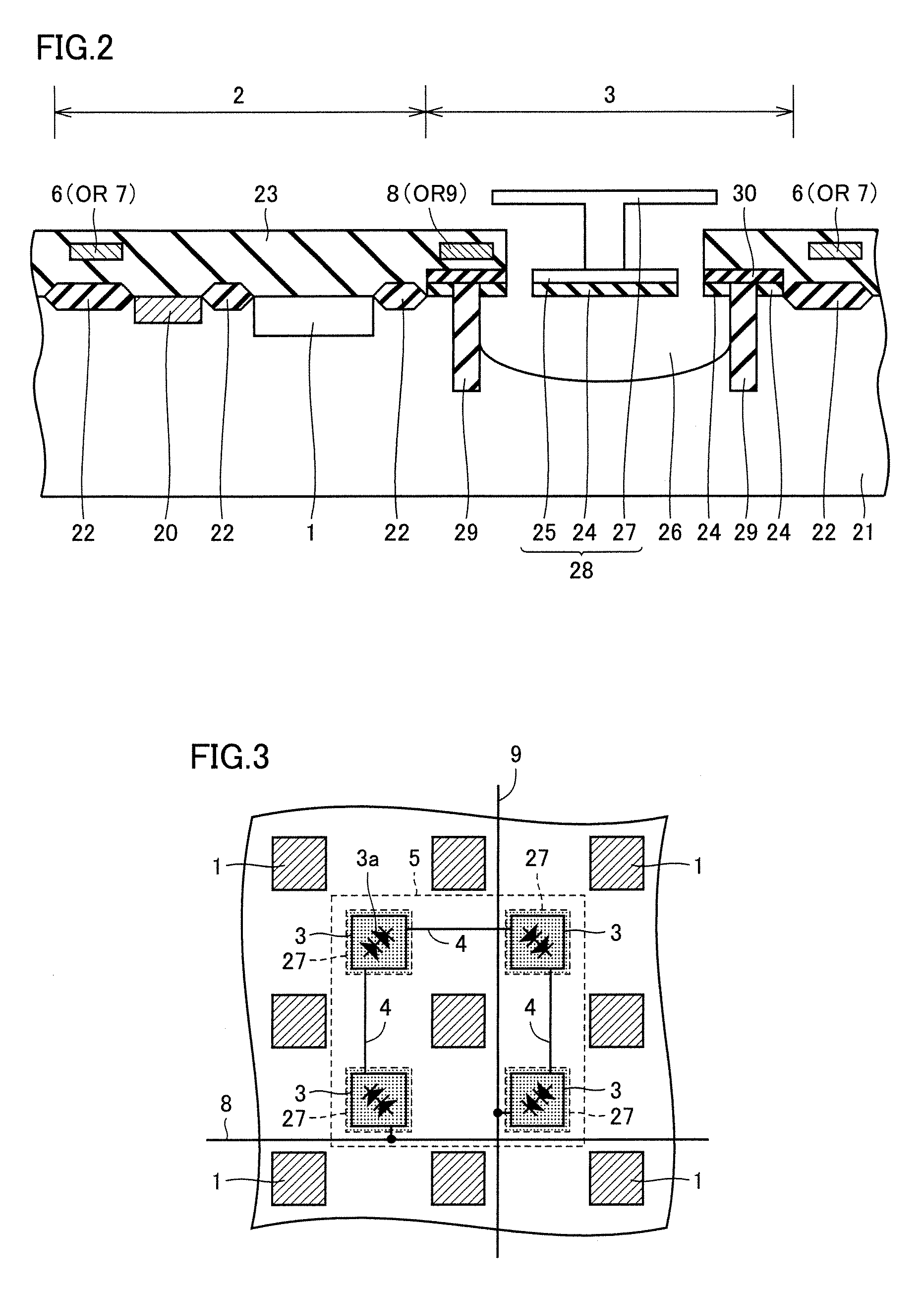
[0044]FIG. 7 is a plan view of a main portion of the present 2-wavelength image sensor in a third embodiment. In FIG. 7 the 2-wavelength image sensor has thermal infrared radiation detecting pixel 5 configured including nine uncooled infrared radiation detectors 3 arranged in three rows and three columns and eight metal interconnections 4 electrically connecting the nine infrared radiation detectors 3 in series. Each uncooled infrared radiation detector 3 includes a single SOI diode 3a. Along each row of thermal infrared radiation detecting pixels 5 horizontal select line 8 is arranged and along each column of thermal infrared radiation detecting pixels 5 vertical signal line 9 is arranged. Thus thermal infrared radiation detecting pixel 5 is electrically configured of nine SOI diodes connected between horizontal select line 8 and vertical signal line 9 in series. Note that although FIG. 7 does not show an interconnection for visible radiation detector 1 and the like, the remainder ...


PUM


Abstract

A 2-wavelength image sensor has a plurality of uniformly dispersedly arranged visible radiation detectors and a plurality of uniformly dispersedly arranged, uncooled infrared radiation detectors, and a single visible radiation detector configures a visible radiation detecting pixel and four series connected infrared radiation detectors configure a thermal infrared radiation detecting pixel. Consequently a visible image can be four times a thermal image in resolution. Furthermore for an infrared image an area increased four times per pixel to receive light can be achieved. As a result the infrared image can be enhanced in temperature resolution.

Description

BACKGROUND OF THE INVENTION[0001]1. Field of the Invention[0002]The present invention relates generally to 2-wavelength image sensors and particularly to 2-wavelength image sensors picking up both visible and infrared images.[0003]2. Description of the Background Art[0004]An optical sensor system utilized in the field of security for detecting human bodies can be improved in performance for detection by combining picking up a visible image and picking up an infrared image. One such sensor system conventionally used is a sensor system that simply combines the two pickup systems of a camera for visible radiation and an infrared camera. However, such a system is large in size and requires a complicated image process between two types of optical images to analyze data. Accordingly there has been a demand for a sensor system capable of picking up both types of images with a single camera.[0005]In connection therewith there has been proposed a 2-wavelength image sensor capable of picking ...

Claims


Application Information

Patent Timeline
IPC IPC(8): G01J5/02
CPCG01J3/36G01J5/22G01J2005/0077H01L27/14603H04N5/3742H01L27/14649H04N5/33H04N5/332H04N5/347H01L27/14645G01J3/2803G01J2005/204H04N23/11H04N25/46H04N25/767
Inventor NAKANISHI, JUNJITAKAMURO, DAISUKE
Owner MITSUBISHI ELECTRIC CORP
Why Eureka
Try Eureka