Method and apparatus for predicting change in an operating state of an electric energy storage device

a technology of electric energy storage and operating state, applied in battery/fuel cell control arrangement, secondary cell servicing/maintenance, instruments, etc., can solve the problems of significant effect on battery service life, reducing service life, and introducing limits to battery charge/discharge performan

Inactive Publication Date: 2007-12-13
GM GLOBAL TECH OPERATIONS LLC
View PDF11 Cites 156 Cited by
  • Summary
  • Abstract
  • Description
  • Claims
  • Application Information

AI Technical Summary

Problems solved by technology

However, cold operating temperature introduces limits in battery charge/discharge performance until temperature of the pack is increased.
A warm battery pack is more able to supply required power to the ve

Method used


Image

  • Method and apparatus for predicting change in an operating state of an electric energy storage device
  • Method and apparatus for predicting change in an operating state of an electric energy storage device
  • Method and apparatus for predicting change in an operating state of an electric energy storage device

Examples


Embodiment Construction

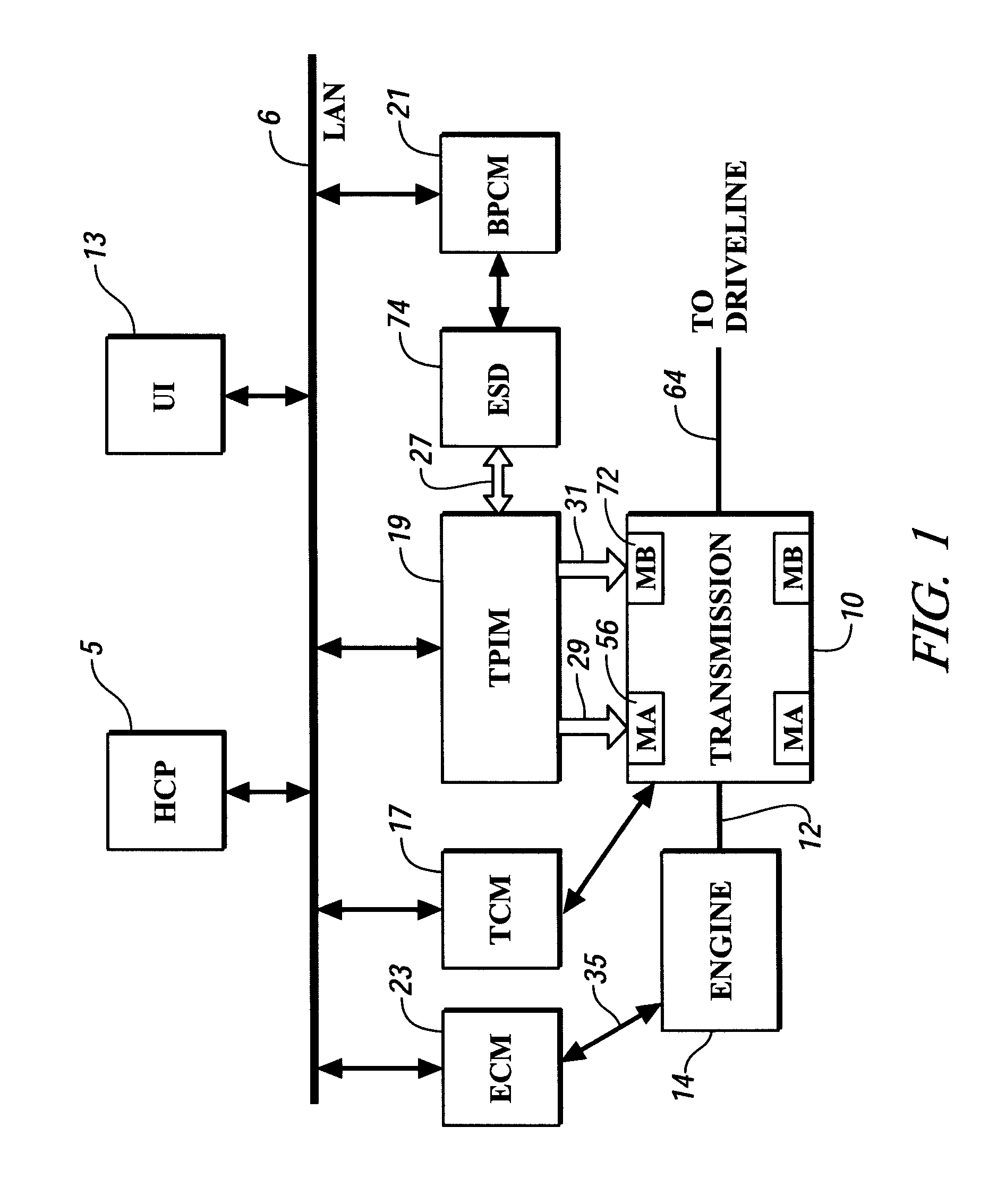
[0012]Referring now to the drawings, wherein the showings are for the purpose of illustrating the invention only and not for the purpose of limiting the same, FIG. 1 shows a control system and an exemplary hybrid powertrain system which has been constructed in accordance with an embodiment of the invention. The exemplary hybrid powertrain system comprises a plurality of torque-generative devices operable to supply motive torque to a transmission device, which supplies motive torque to a driveline. The torque-generative devices preferably comprise an internal combustion engine 14 and first and second electric machines 56, 72 operable to convert electrical energy supplied from an electrical storage device 74 to motive torque. The exemplary transmission device 10 comprises a two-mode, compound-split electro- mechanical transmission having four fixed gear ratios, and includes a plurality of gears operable to transmit the motive torque to an output shaft 64 and driveline through a plural...


PUM


Abstract

A method for predicting change in an operating state, e.g. state of life, for an electrical energy storage device includes establishing a plurality of values for an operating parameter, e.g. current, of the electrical energy storage device and, for each respective value, determining a corresponding change in the operating state for the energy storage device based upon the respective value. Preferably, change in the state of life is determined based upon an integration of electrical current, a depth of discharge of the energy storage device, and an operating temperature factor of the electrical energy storage device.

Description

TECHNICAL FIELD[0001]This invention pertains generally to an electrical energy storage device. More particularly, the invention is concerned with predicting effects upon an electrical energy storage device.BACKGROUND OF THE INVENTION[0002]Various hybrid propulsion systems for vehicles use electrical energy storage devices to supply electrical energy to electrical machines, which are operable to provide motive torque to the vehicle, often in conjunction with an internal combustion engine. An exemplary hybrid powertrain architecture comprises a two-mode, compound-split, electromechanical transmission which utilizes an input member for receiving power from a prime mover power source and an output member for delivering power from the transmission to a vehicle driveline. First and second electric machines, i.e. motor / generators, are operatively connected to an energy storage device for interchanging electrical power therebetween. A control unit is provided for regulating the electrical p...

Claims


Application Information

Patent Timeline
IPC IPC(8): G01N27/416
CPCH01M10/42G01N27/4163B60L3/12B60L15/20B60L2240/429B60L2240/549B60L2240/80B60L2260/42B60L2260/46B60L2260/50B60L58/12B60L58/16Y02E60/10Y02T10/64Y02T10/70Y02T10/72B60L3/0046
Inventor ZETTEL, ANDREW M.HEAP, ANTHONY H.
Owner GM GLOBAL TECH OPERATIONS LLC
Why Eureka
Try Eureka