Centralized optical-fiber-based RFID systems and methods

Inactive Publication Date: 2007-12-13
CORNING CABLE SYST LLC
View PDF99 Cites 32 Cited by
  • Summary
  • Abstract
  • Description
  • Claims
  • Application Information

AI Technical Summary

Benefits of technology

[0011]One aspect of the invention is an optical-fiber-based RFID system for tracking one or more RFID tags each having information stored therein. The system includes a picocellular coverage area made up of an array of one or more picocells. The picocells are formed by corresponding one or more transponders. Each transponder has an antenna and each is adapted to convert electrical RF signals to optical RF signals and vice versa. The system also includes one o

Problems solved by technology

This conventional approach to RFID is still equipment-intensive and is also labor-intensive, and tends to be expensive to implement and maintain.

Method used


Image

  • Centralized optical-fiber-based RFID systems and methods
  • Centralized optical-fiber-based RFID systems and methods
  • Centralized optical-fiber-based RFID systems and methods

Examples


Embodiment Construction

[0030]Reference is now made in detail to the present preferred embodiments of the invention, examples of which are illustrated in the accompanying drawings. Whenever possible, the same or analogous reference numbers are used throughout the drawings to refer to the same or like parts.

I. Basic Optical-Fiber-Based RFID System

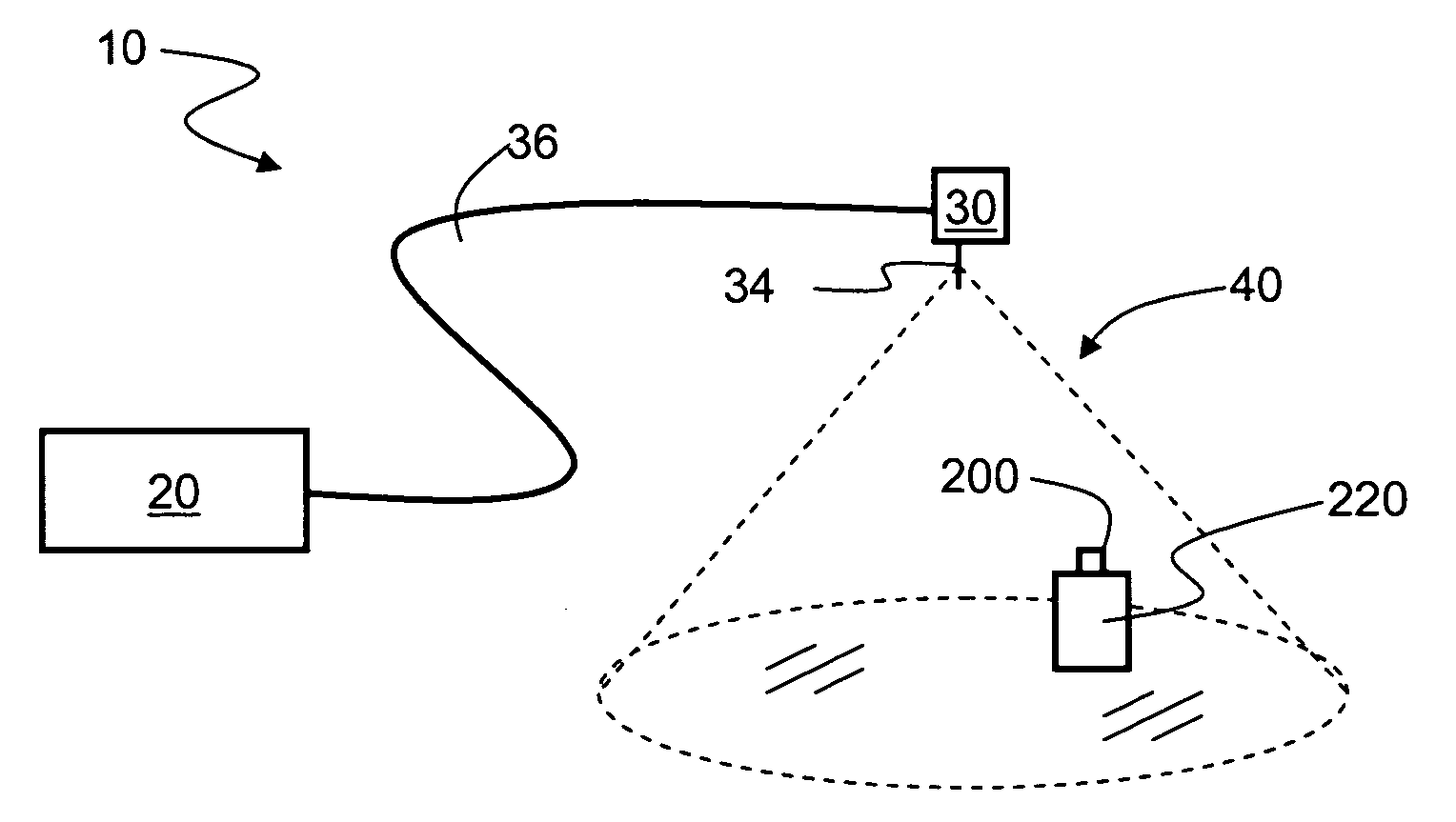
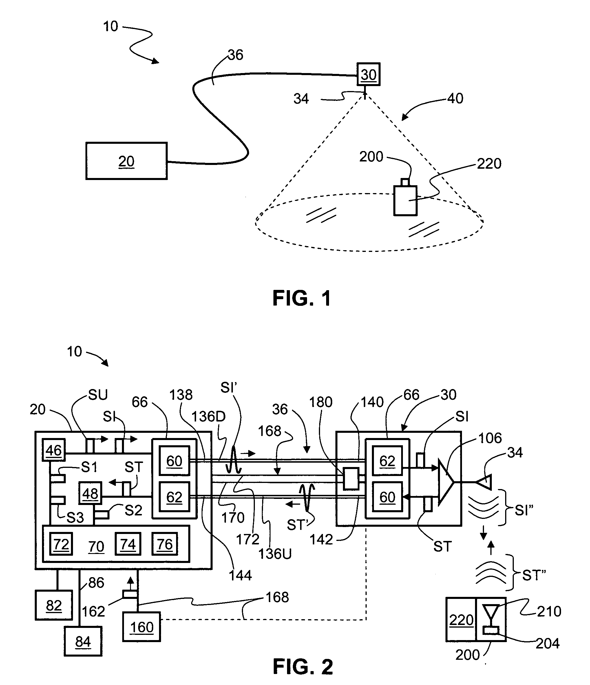
[0031]FIG. 1 is a schematic diagram of a generalized embodiment of an optical-fiber-based RFID system 10 according to the present invention. System 10 includes a RFID reader unit (“RFID reader”) 20, a transponder unit (“transponder”) 30 that includes an antenna 34, and an optical fiber RF communication link 36 that optically couples the RFID reader to the transponder. As discussed below, RFID system 10 has picocell 40 substantially centered about antenna 34. The discussion below is assumes for the sake of illustration that antenna 34 is located in close proximity to the other components making up transponder 30 so that the location picocell 40 is said to correspond...


PUM


Abstract

The optical-fiber-based radio-frequency identification (RFID) system includes one or multiple RFID readers optically coupled to one or more transponders via respective one or more optical fiber RF communication links. The transponders are each adapted to receive electromagnetic RF tag signals from RFID tags within the associated picocell and transmit optical RF tag signals to the corresponding RFID reader over the corresponding optical fiber RF communication link. The RFID reader then converts the optical RF tag signals to electrical RFID tag signals, and extracts the RFID tag information from the RFID tag signals. The transponders can be arranged spaced apart along the length of one or more optical fiber cables made up of pairs of downlink and uplink optical fibers that constitute the optical fiber RF communication links.

Description

FIELD OF THE INVENTION[0001]The present invention relates generally to radio-frequency identification (RFID) systems, and in particular relates to centralized RFID systems and methods employing RF transmission over optical fiber.BACKGROUND OF THE INVENTIONI. Wireless Picocellular Systems[0002]Wireless communication is rapidly growing, with ever-increasing demands for high-speed mobile data communication. As an example, so-called “wireless fidelity” or “WiFi” systems and wireless local area networks (WLANs) are being deployed in many different types of areas (coffee shops, airports, libraries, etc.). Wireless communication systems communicate with wireless devices called “clients,” which must reside within the wireless range or “cell coverage area” in order to communicate with the access point device.[0003]One approach to deploying a wireless communication system involves the use of “picocells,” which are radio-frequency (RF) coverage areas having a radius in the range from about a f...

Claims


Application Information

Patent Timeline
IPC IPC(8): G08B13/14
CPCG06K7/0008G06K19/0723H04B10/25752G06K2017/0045G06K19/0728
Inventor EASTON, MARTYN N.SAUER, MICHAEL
Owner CORNING CABLE SYST LLC
Why Eureka
Try Eureka