Circularly polarized antenna device
a technology of circular polarization and antenna device, which is applied in the direction of polarised antenna unit combination, electromagnetic radiation sensing, instruments, etc., can solve the problem of large overall configuration area, and achieve the effect of simple configuration and good axial ratio
- Summary
- Abstract
- Description
- Claims
- Application Information
AI Technical Summary
Benefits of technology
Problems solved by technology
Method used
Image

Examples
first embodiment
(1) First Embodiment
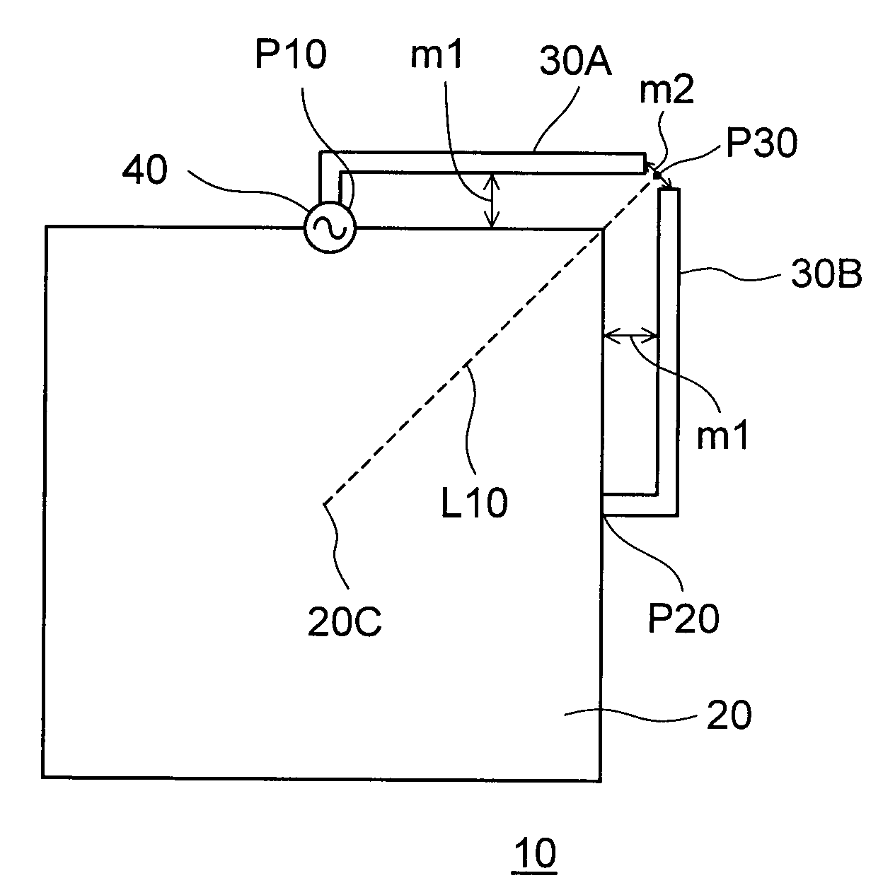
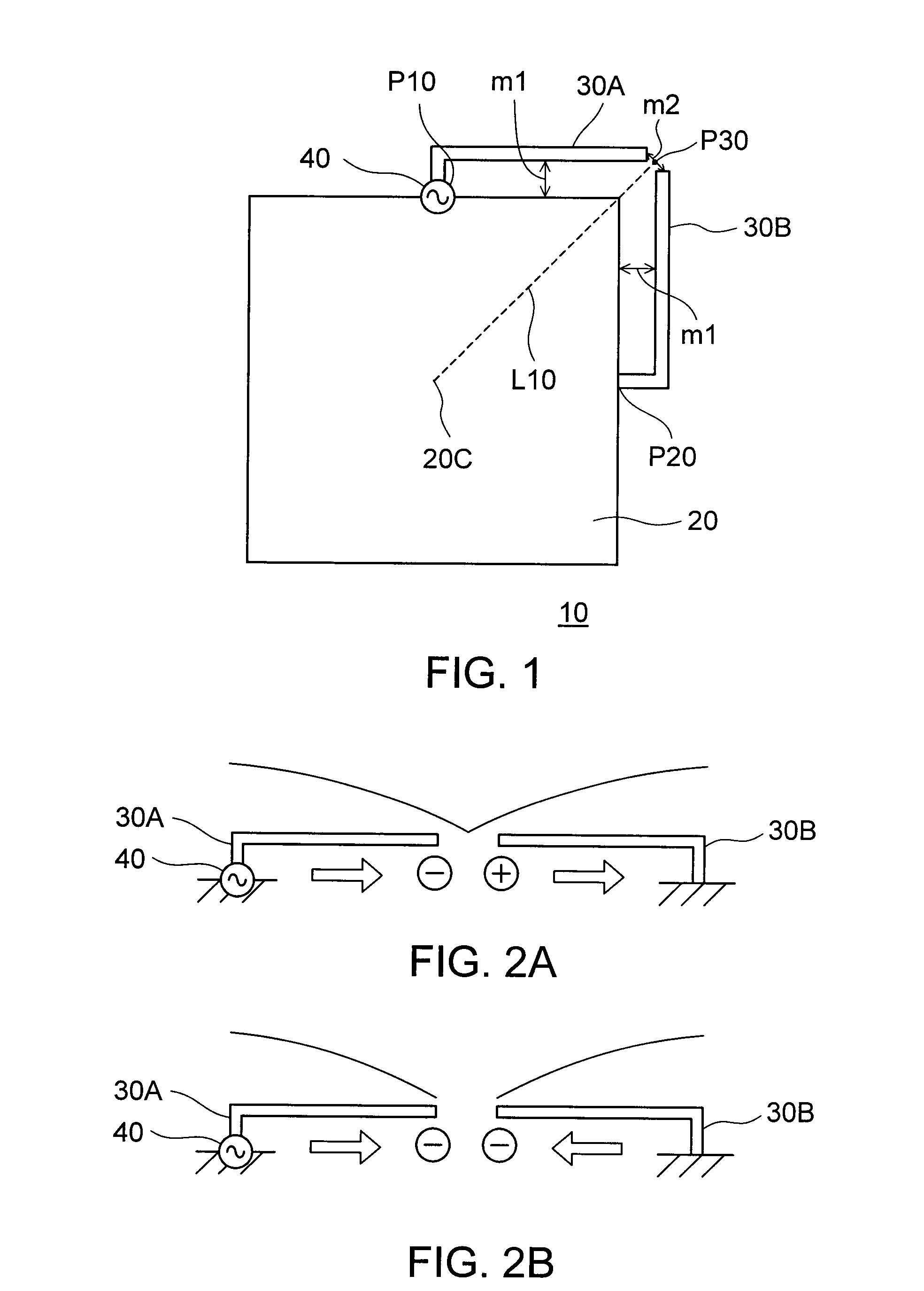
[0043]FIG. 1 is a diagram showing a general configuration of a circularly polarized antenna device 10 according to a first embodiment of the present invention. The circularly polarized antenna device 10 shown in FIG. 1 is provided with: a quadrate-shaped conductive ground plane 20; L-shaped monopole conductive elements 30A and 30B having lengths of approximately ¼ wavelength and respectively connected to a point P10 that is bilaterally symmetrical with respect to sides of a periphery of the conductive ground plane 20 and a position P20 having a 90-degree angular difference from the point P10 with respect to a center 20C of the conductive ground plane 20; and a feeding point 40 provided at the connecting point P10 of one of the L-shaped monopole conductive elements 30A. The two L-shaped monopole conductive elements 30A and 30B are approximately symmetrical with respect to a line segment L10 connecting a midpoint P30 between open ends of the L-shaped monopole condu...
second embodiment
(2) Second Embodiment
[0061]FIG. 9 is a diagram showing a general configuration of a circularly polarized antenna device 50 according to a second embodiment of the present invention. The second embodiment is arranged so that another set of two L-shaped monopole conductive elements 60A and 60B, and a feeding point 70, is newly provided at a position that is diagonal to the set shown in FIG. 1.
[0062]By newly providing another set of the two L-shaped monopole conductive elements 60A and 60B, and the feeding point 70 at a diagonal position, the symmetrical property of the shape may be preserved, and in the same manner as the circularly polarized antenna device 10 shown in FIG. 1, circularly polarized waves having a good axial ratio in a maximum radiation direction, the wideband frequency and wide angle characteristics may be generated.
[0063]In addition, when normally using same antennas for both transmission and reception, two sets including conductive ground planes will be required and ...
third embodiment
(3) Third Embodiment
[0067]FIG. 11 is a diagram showing a general configuration of a circularly polarized antenna device 80 according to a third embodiment of the present invention. The circularly polarized antenna device 80 shown in FIG. 11 is provided with: a quadrate-shaped conductive ground plane 20; a T-shaped conductive element 90 having a length between an open end and other open end thereof of approximately ½ wavelength, and disposed at a point P10 that is bilaterally symmetrical with respect to sides of a periphery of the conductive ground plane 20; a feeding point 40 provided at the connecting point P10 of the conductive ground plane 10 and the T-shaped monopole conductive element 90; two L-shaped monopole conductive elements 100 and 110 having lengths of approximately ¼ wavelength and respectively connected to positions P20 and P40 that have angular differences of plus-minus 90 degrees from the connection point P10 of the T-shaped conductive element 90 with respect to a ce...
PUM
 Abstract
Description
Claims
Application Information