
Method for motion detection and method and system for supporting analysis of software error for video systems

Inactive Publication Date: 2007-12-13
HITACHI LTD
View PDF0 Cites 25 Cited by
  • Summary
  • Abstract
  • Description
  • Claims
  • Application Information

AI Technical Summary

Benefits of technology

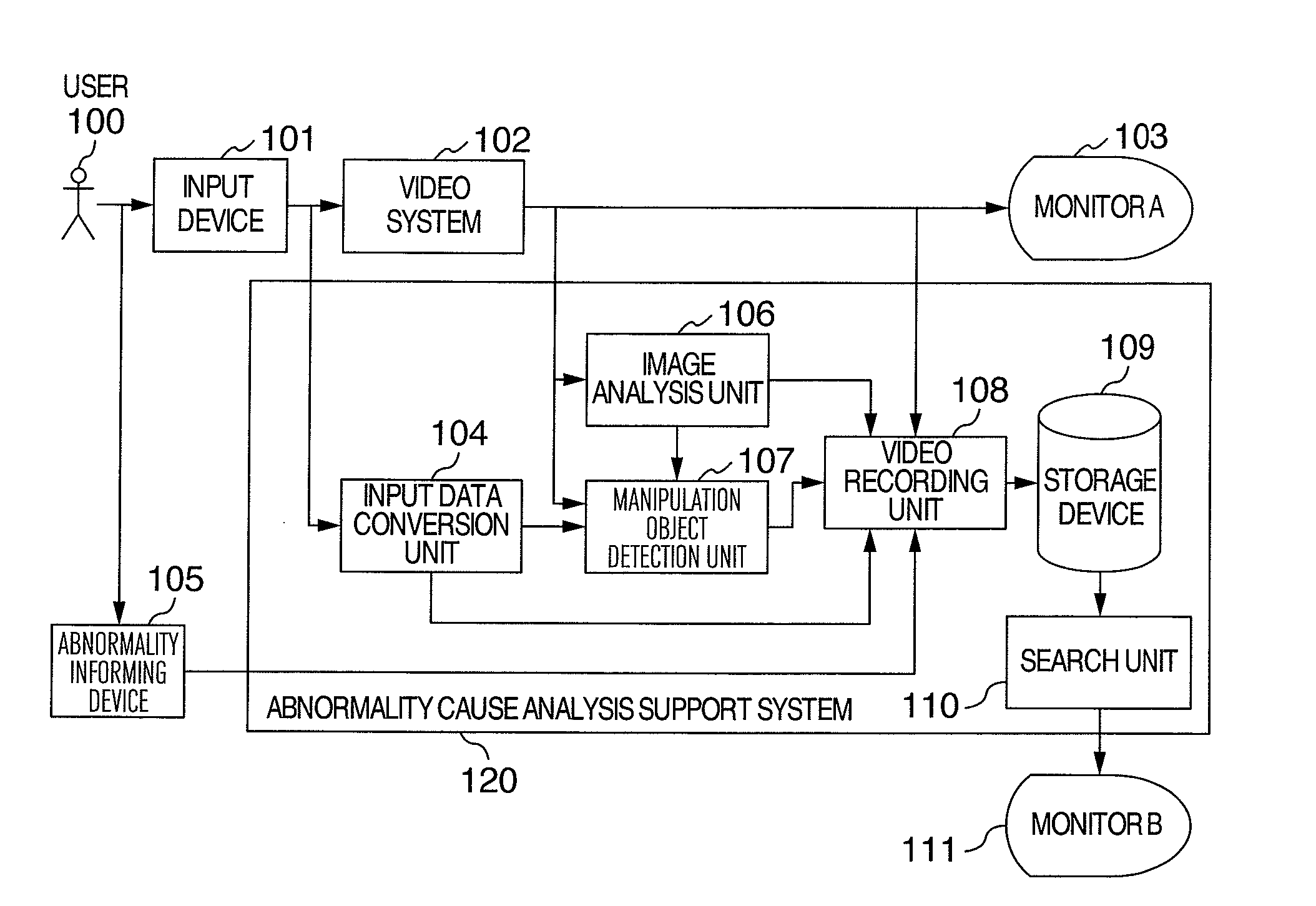
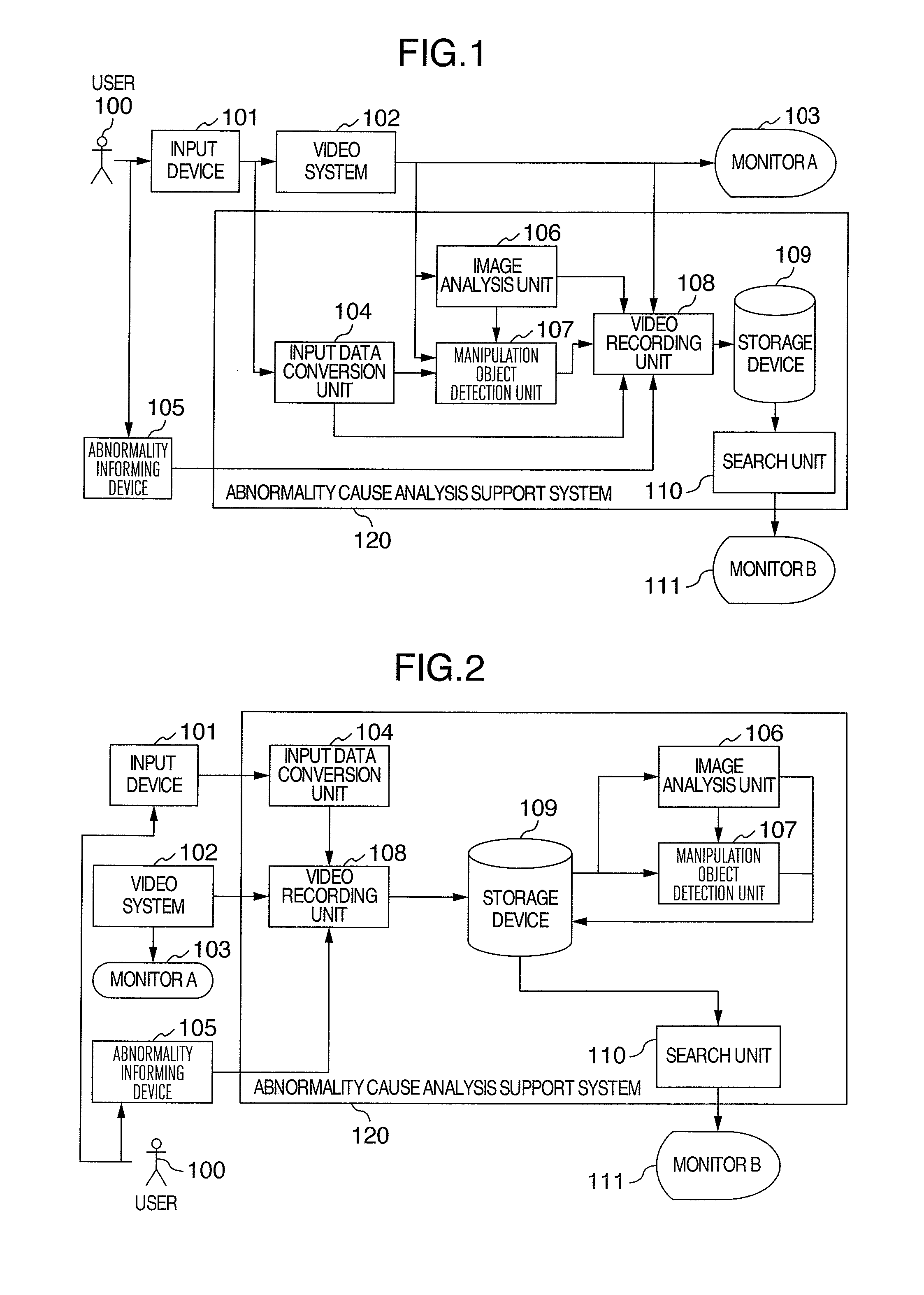
[0007]To solve the above problems experienced with the conventional techniques, it is an object of this invention to provide a method for detecting moving objects in a video and a method and system for supporting the analysis of causes for abnormalities that have occurred in the video system. In a video system capable of manipulating objects in the video, the method of this invention detects moving objects in the video output from the video system and, based on the information about the detected moving objects, makes it possible to compare videos and operation logs for the locations where the same abnormalities have occurred, thus facilitating the analysis of possible causes of abnormalities.
[0010]Since according to the invention it is possible to determine whether the moving object in the video is moving as a result of manipulation by the user and, for abnormalities found during the test on the video system, can compare videos and operation logs of the locations where the same abnormalities have occurred, the analysis of causes for abnormalities can be performed more easily.

Problems solved by technology

This process takes significant time and labor.
Particularly, when the system test is performed parallelly by many staffs, the conventional process takes particularly large amounts of time and labor.
Another problem of the conventional techniques is that the videos and operation logs recorded during the video system test can only be analyzed one at a time, making it impossible to check and compare a plurality of similar abnormalities that have occurred at different locations.

Method used


Image

  • Method for motion detection and method and system for supporting analysis of software error for video systems
  • Method for motion detection and method and system for supporting analysis of software error for video systems
  • Method for motion detection and method and system for supporting analysis of software error for video systems

Examples


Embodiment Construction

[0021]Now, the method of detecting a moving object in a video and the video system abnormality cause analysis support method and system according to this invention will be described in detail by referring to the accompanying drawings of example embodiments.

[0022]The embodiments of this invention that are described in the following are intended to facilitate an analysis of causes for abnormalities that are found during a test of a video system capable of manipulating an object in a video. Thus, the embodiments of this invention have an image analysis processing unit and a manipulation object detection processing unit connected to a video system to record videos, operation logs and images of the manipulation object during the test and to search the recorded data to display only desired data on the monitor.

[0023]During the test of the video system, the embodiments of this invention not only record the output video from the video system and the user operation logs but also record abnorm...


PUM


Abstract

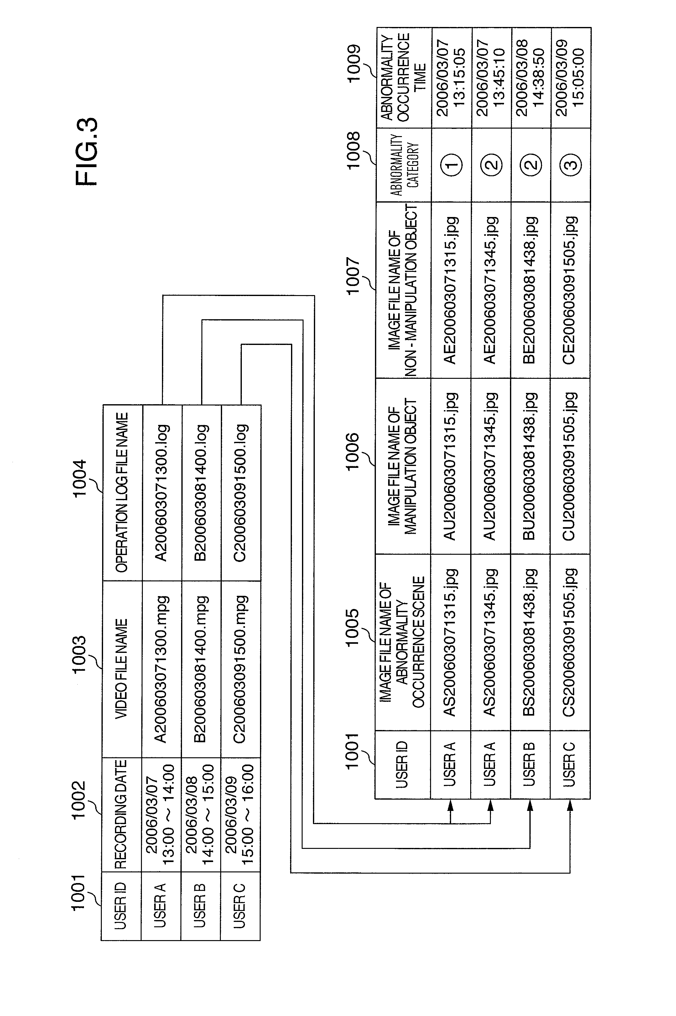
Method and system for facilitating analysis of causes of abnormalities found during a test on a video system. Video output from the system during the test, operation log of a test worker, and images generated by image analysis unit analyzing characteristic quantities of the video output from the system and determining points of change of the video and moving objects in the video, are recorded in storage device. Relation between the direction of the moving objects in the video and the direction of user input operations is checked and the moving objects in the video are classified into user-manipulation objects and non-manipulation objects and recorded. Abnormality occurrence locations are recorded. Recorded data are searched, classified and displayed by using as a key the abnormality categories, operation patterns of the operation logs, images of abnormality occurrence scenes and images of manipulation objects.

Description

INCORPORATION BY REFERENCE[0001]The present application claims priority from Japanese application JP 2006-137847 filed on May 17, 2006, the content of which is hereby incorporated by reference into this application.BACKGROUND OF THE INVENTION[0002]The present invention relates to a method for motion detection and method and System for supporting Analysis of software error for video systems. More specifically, in a video system capable of manipulating objects in video or image data, the invention relates to a method of detecting a moving object in a video or image suited for use in supporting an analysis of causes of abnormalities or faults that occur when generating video data or objects in video and also to a software error analysis support method and system.[0003]In a video system in which a user of a home video game machine or virtual reality system performs irregular input operations, if an abnormality or fault should occur as a result of some operations, it may be difficult to ...

Claims


Application Information

Patent Timeline
IPC IPC(8): H04N5/14A63F13/52
CPCG06T7/20G06T2207/30241G06T2207/10016H04N17/04H04N17/00
Inventor HIRAYAMA, MASAKIOKI, YASUYUKI
Owner HITACHI LTD
Learn More