Light guide plate

Inactive Publication Date: 2007-12-13
JENG SHIANG PRECISION IND
View PDF9 Cites 17 Cited by
  • Summary
  • Abstract
  • Description
  • Claims
  • Application Information

AI Technical Summary

Benefits of technology

[0011]Therefore, the object of the present invention is to provide a light guide plate that is capable of

Problems solved by technology

However, distribution of the light-reflecting dots on the bottom surface and the sizes of the light-reflecting dots are not uniform such that the light beams are diffused unevenly, resulting in a relatively large loss of energy and poor light uniformity.
1. Since the first and second V-shaped grooves 3, 4 form elongated structures respectively on the first and second surfaces, minor adjustments on local areas where optical characteristics are relatively poor cannot be provided thereby. For instance, luminance of the light beams exiting the light guide plate is higher for regions of the modified conventional light guide plate proximate to the light source 1 than regions distal from the light source 1. However, the elongated structures formed by the first and second V-sh

Method used


Image

  • Light guide plate
  • Light guide plate
  • Light guide plate

Examples


Embodiment Construction

[0023]Before the present invention is described in greater detail, it should be noted herein that like elements are denoted by the same reference numerals throughout the disclosure.

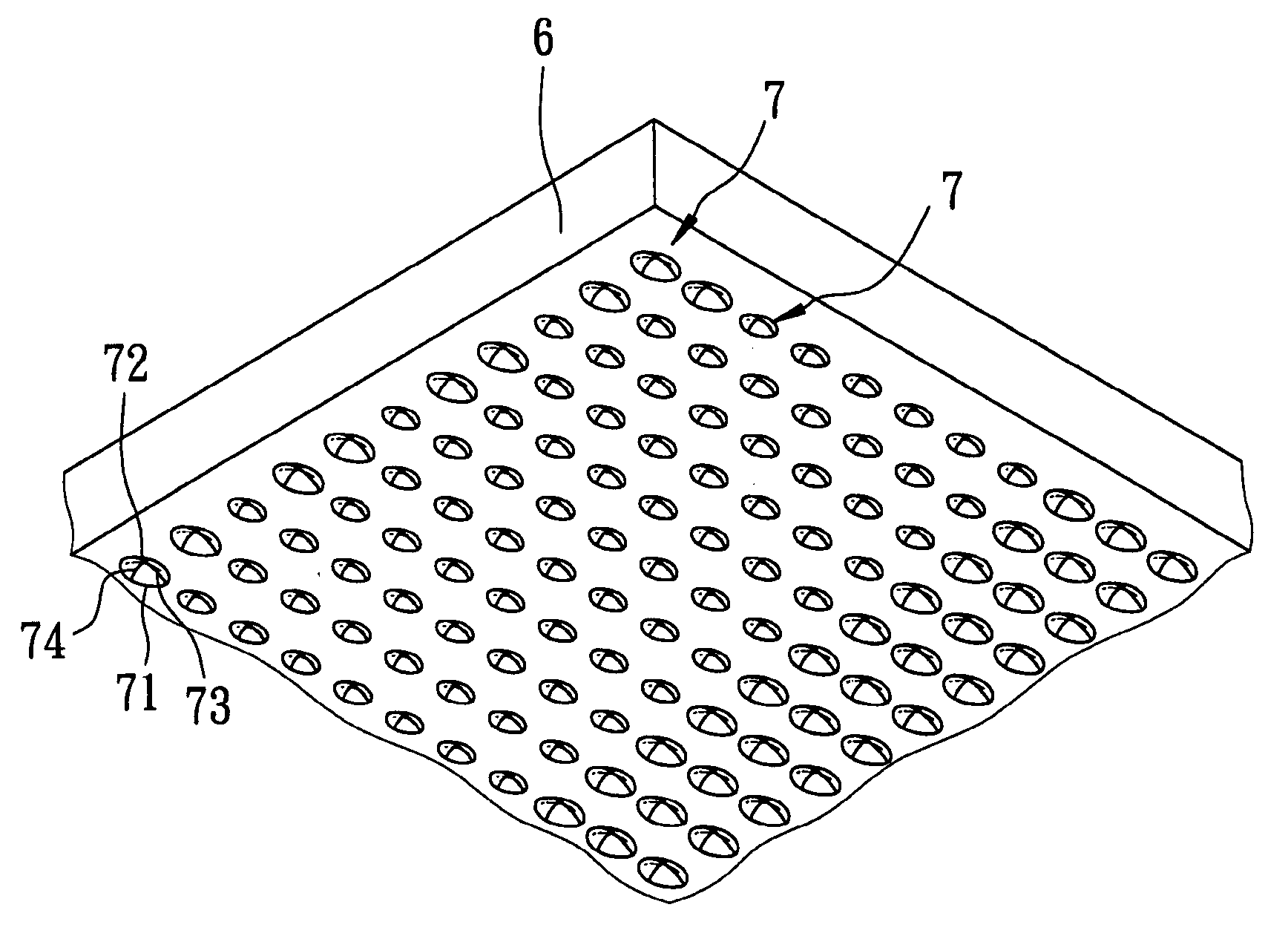
[0024]As shown in FIG. 3 and FIG. 4, the first preferred embodiment of a light guide plate according to the present invention includes a plate body 6 and a plurality of light-guiding structures 7. The light guide plate is adapted for use with at least one light source 8 that is capable of providing source light beams, and that defines a light-emitting axis (I).

[0025]The light-guiding structures 7 are distributed on the plate body 6. Each of the light-guiding structures 7 is in a substantially quadrilateral pyramidal form, and includes a quadrilateral lower end 71 that has four corners (a), (b), and a tapered upper end 72 that is disposed opposite to the lower end 71. A first pair of the corners (a) is aligned in the direction of the light-emitting axis (I), and a second pair of the corners (b) is aligned ...


PUM


Abstract

A light guide plate is adapted for use with at least one light source that is capable of providing source light beams. The light guide plate includes a plate body, and a plurality of light-guiding structures that are distributed on the plate body. Each of the light-guiding structures is in a substantially quadrilateral pyramidal form, and includes a quadrilateral lower end that has four corners, and a tapered upper end that is disposed opposite to the lower end. Each of the light-guiding structures further includes four sides, each of which is defined by the upper end and a corresponding adjacent pair of the corners, adjacent ones of the sides being interconnected.

Description

CROSS-REFERENCE TO RELATED APPLICATION[0001]This application claims priority of Taiwanese Application No. 095120231, filed on Jun. 7, 2006.BACKGROUND OF THE INVENTION[0002]1. Field of the Invention[0003]The invention relates to a light guide plate, more particularly to a light guide plate including a plurality of light-guiding structures.[0004]2. Description of the Related Art[0005]A conventional light guide plate utilizes total internal reflection to make light beams provided by a light source propagate from a first edge surface of the light guide plate to a second edge surface of the light guide plate opposite to the first edge surface. Since the light guide plate is provided for distributing the light beams to form a surface light source, where light beams exit the light guide plate from a light-exit surface, a bottom surface of the light guide plate opposite to the light-exit surface is normally etched with a plurality of light-reflecting dots such that light beams encountering ...

Claims


Application Information

Patent Timeline
IPC IPC(8): F21V7/04
CPCG02B6/0061G02B6/0036
Inventor LIN, CHIH-TSUNGSU, TZU-WEN
Owner JENG SHIANG PRECISION IND
Why Eureka
Try Eureka