
System and method of determining the exposed field of view in an x-ray radiograph

a radiograph and exposed field technology, applied in the field of x-ray systems and methods, can solve the problems of mobile or portable radiography systems, inability to receive feedback data from positioners, and relying solely on image-based algorithms or hardware-based algorithms to determine the exposed field of view

Inactive Publication Date: 2007-12-13
GENERAL ELECTRIC CO
View PDF3 Cites 13 Cited by
  • Summary
  • Abstract
  • Description
  • Claims
  • Application Information

AI Technical Summary

Benefits of technology

[0007] Therefore, there is a need in the art for more precisely determining the exposed field of view in an X-ray radiograph using both an image-based algorithm and a hardware-based positioner feedback algorithm. (positioner feedback-based algorithm)

Problems solved by technology

In other implementations, feedback data from the positioner is completely unavailable such as in mobile or portable radiography systems because the image processing chain is not usually integrated with the positioner and therefore has no knowledge of the collimator coordinates and collimation edges.
Since each approach of using an image-based algorithm or a hardware-based algorithm to determine the exposed field of view in an X-ray radiograph has both its advantages and disadvantages, relying solely on either the image-based algorithm or the hardware-based algorithm to determine the exposed field of view is not optimal.

Method used


Image

  • System and method of determining the exposed field of view in an x-ray radiograph
  • System and method of determining the exposed field of view in an x-ray radiograph
  • System and method of determining the exposed field of view in an x-ray radiograph

Examples


Embodiment Construction

[0031] In the following detailed description, reference is made to the accompanying drawings that form a part hereof, and in which is shown by way of illustration specific embodiments which may be practiced. These embodiments are described in sufficient detail to enable those skilled in the art to practice the embodiments, and it is to be understood that other embodiments may be utilized and that logical, mechanical, electrical and other changes may be made without departing from the scope of the embodiments. The following detailed description is, therefore, not to be taken in a limiting sense.

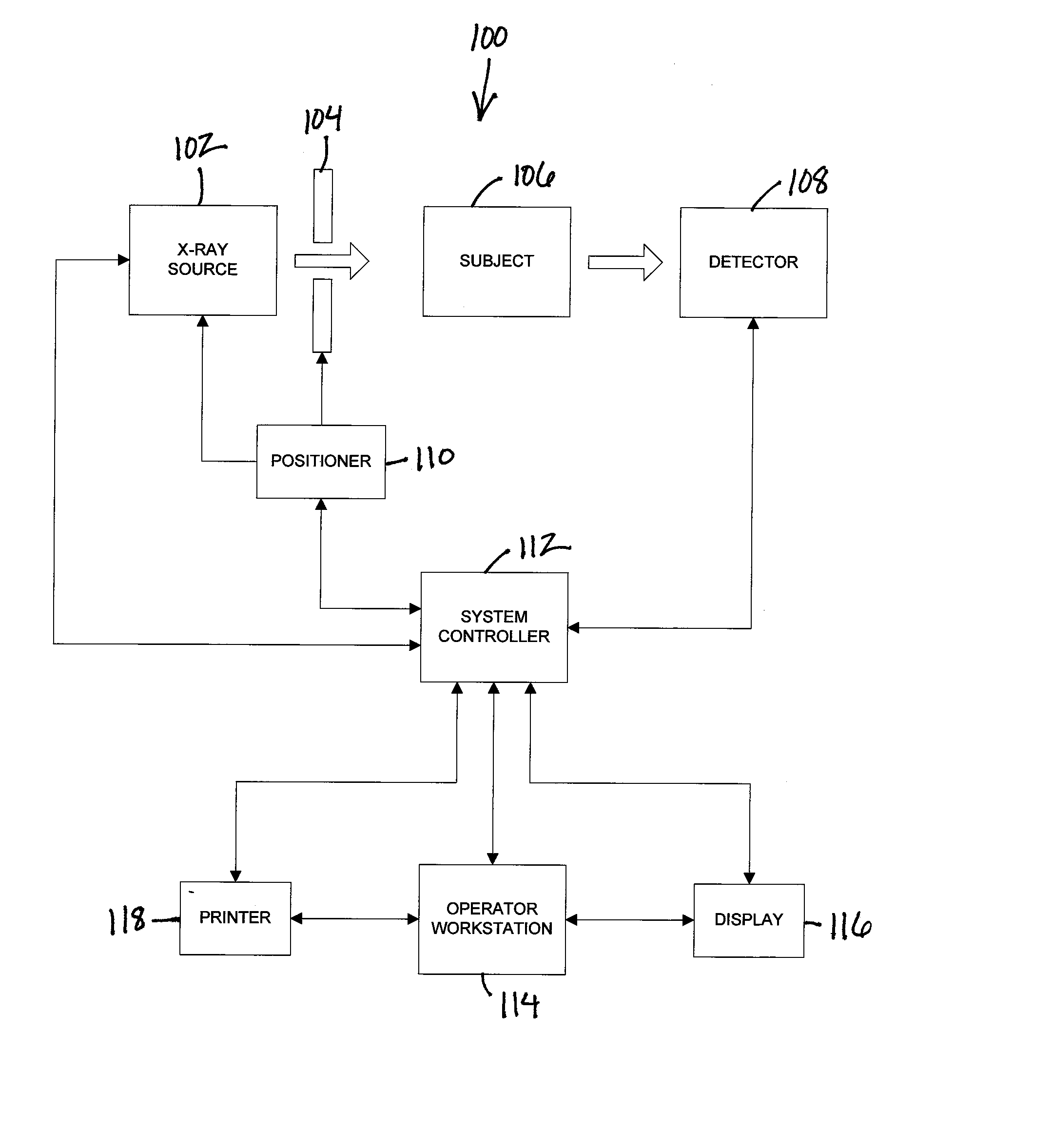
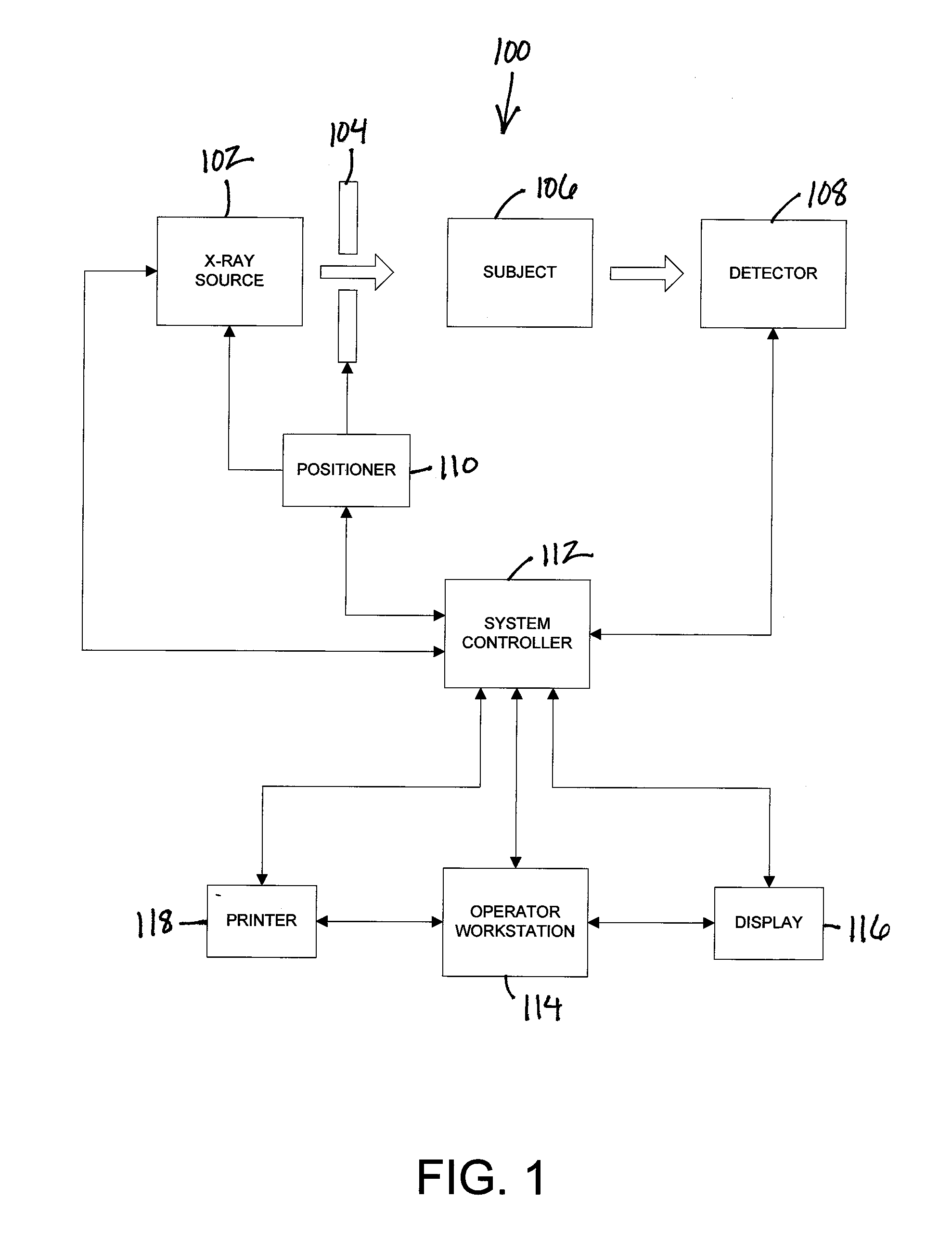
[0032] Referring now to the drawings, FIG. 1 illustrates a block diagram of an exemplary embodiment of a radiography system 100. The system 100 is configured for determining the exposed field of view of an image generated by the radiography system. The radiography system 100 includes an X-ray source 102, a collimator 104 adjacent to the X-ray source 102, a subject 106 to be imaged, a detector...


PUM


Abstract

A system and method of determining the exposed field of view of a radiography image based on various parameters such as image content data, positioner feedback data, or any combination thereof, with no need for user intervention.

Description

CROSS-REFERENCE TO RELATED APPLICATIONS [0001] This application is based on and claims the benefit of U.S. Provisional Patent Application No. 60 / 947,180, filed Jun. 29, 2007, and is also a continuation-in-part of and claims priority to U.S. patent application Ser. No. 11 / 023,244, filed Dec. 24, 2004, the disclosures of which are incorporated herein by reference.BACKGROUND OF THE INVENTION [0002] This disclosure relates generally to X-ray systems and methods, and more particularly to a system and method of determining the exposed field of view in an X-ray radiograph. [0003] In an X-ray or digital radiography system, an X-ray beam is generated from an X-ray source and projected through a subject to be imaged onto an X-ray detector. Between the X-ray source and the X-ray detector is a collimator that defines and restricts the dimensions and direction of the X-ray beam from the X-ray source onto the X-ray detector. [0004] The image projected onto the X-ray detector has edges that define...

Claims


Application Information

Patent Timeline
Patent Type & Authority Applications(United States)
IPC IPC(8): G06K9/36
CPCA61B6/06G06T7/0083G06T2207/10081G06T2207/30004G06T2207/20132G06T2207/20144G06T2207/10116G06T7/12G06T7/194
Inventor JABRI, KADRI NIZARUPPALURI, RENUKASRINIVAS, YOGESHKRISHNAKUMAR, KARTHIK KUMAR
Owner GENERAL ELECTRIC CO
Learn More