Method of operating and optimising a WDM transmission system and computer program product

a transmission system and computer program technology, applied in the field of operating and optimising a wdm transmission system and computer program product, can solve the problems of high cost, complex modulation format adapted to the transmission line by electrical/optical devices, and high impairment so as to improve the performance of the optical wdm transmission system

Active Publication Date: 2007-12-13
META PLATFORMS INC
View PDF2 Cites 3 Cited by
  • Summary
  • Abstract
  • Description
  • Claims
  • Application Information

AI Technical Summary

Benefits of technology

[0009] It is the object of the present invention to provide methods of the above-identified kind, which can be used to improve performance of an optical WDM transmission system, in particular for upgrading the system to operation at higher bit rates, in a cost-effective way.

Problems solved by technology

Optical Wavelength Division Multiplex (WDM) transmission systems are highly impaired by the combined effects of dispersion and Kerr non-linearities.
The corresponding issue of system migration to higher bit rates particularly involves dispersion management, the constraints of which are rather tight at bit rates of 40+ Gbit / s.
Furthermore, system migration to higher bit rates generally requires modified dispersion management solutions, since a dispersion map optimised for 10 Gbit / s generally will not be compatible with 40 Gbit / s even though total cumulated dispersion is well adjusted.
When migrating a low bit rate system to higher bit rates, it is known to add system complexity at both transmitter and receiver side to generate adapted advanced modulation formats that can be operated while preserving the dispersion map originally designed for the lower bit rate.
Furthermore, the use of complex modulation formats adapted to the transmission line by means of electrical / optical devices has proved very costly.

Method used


Image

  • Method of operating and optimising a WDM transmission system and computer program product
  • Method of operating and optimising a WDM transmission system and computer program product

Examples


Embodiment Construction

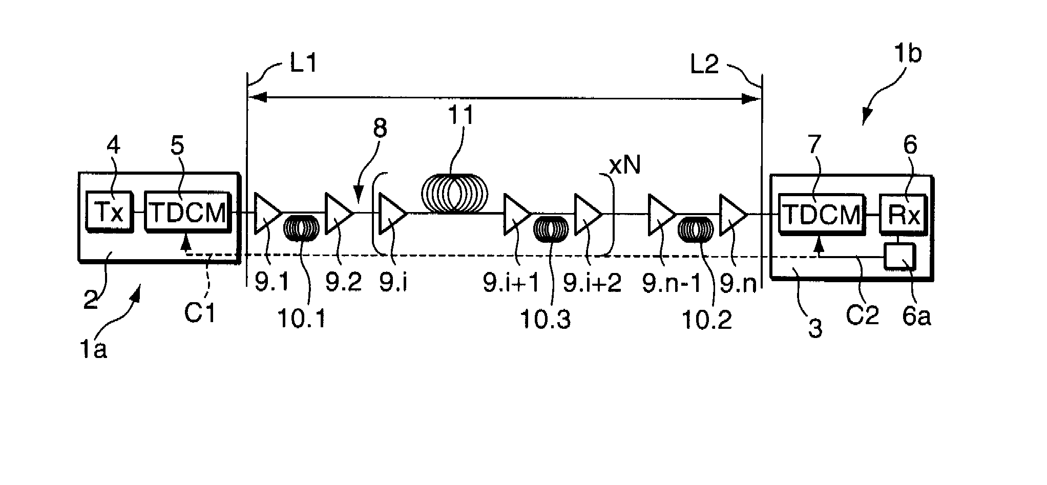
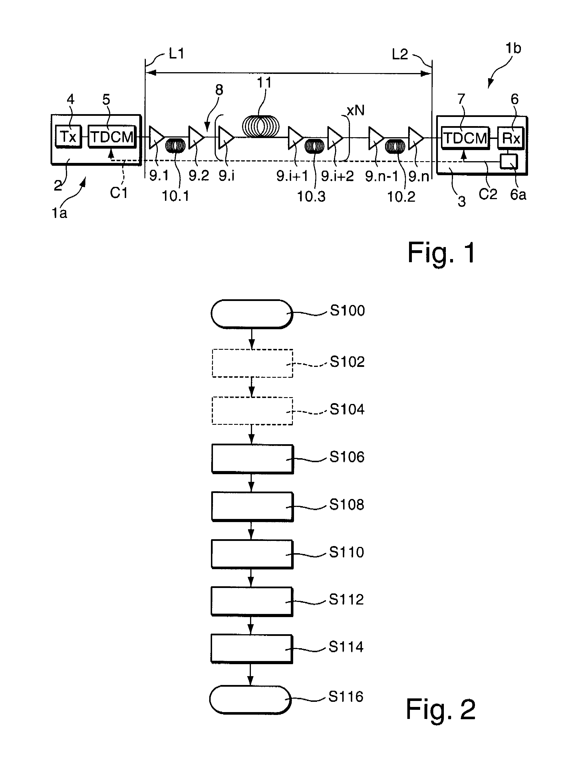
[0038]FIG. 1 is a schematic diagram of an optical Wavelength Division Multiplex (WDM) transmission system 1. The system 1 according to the embodiment of FIG. 1 comprises a first transponder 2 on a transmitter side 1a of the WDM transmission system 1, and a second transponder 3 on a receiver side 1b of the WDM transmission system 1. First transponder 2 comprises a transmitter 4 in operative connection with a Tuneable Dispersion Compensation Module (TDCM) 5. Second transponder 3 comprises a receiver 6 in operative connection with monitoring means 6a and with a further Tuneable Dispersion Compensation Module (TDCM) 7.

[0039] According to the embodiment shown, the transmitter 4 and the receiver 6 are connected by means of a dispersive and nonlinear optical transmission line 8, i.e. an optical fibre introducing dispersion on optical signals transmitted from the transmitter 4 to the receiver 6. The optical transmission line 8 includes a number of amplifier stages 9.1, . . . , 9.i, . . . ,...


PUM


Abstract

A method of operating a WDM transmission system (1) with at least one transmitter (4) and at least one receiver (6) connected by means of a dispersive transmission line (8). The proposed method comprises the successive steps of successively:
    • a) setting a tuneable dispersion pre-compensation value at a transmitter-side Tuneable Dispersion Compensation Module (5) in operative connection with the transmitter to a first predetermined value (PRE°);
    • b) setting or adjusting a tuneable dispersion post-compensation value at a receiver-side Tuneable Dispersion Compensation Module (7) in operative connection with the receiver to a second value (POST°) in order to optimise at least one characteristic (monitored performance like BER, eye opening, Q factorBER) of a transmitted signal at the receiver; and then c) simultaneously tuning the transmitter-side Tuneable Dispersion Compensation Module and the receiver-side Tuneable Dispersion Compensation Module with opposite respective dispersion shifts in order to further optimise said characteristic of the transmitted signal.

Description

[0001] The invention is based on a priority application EP 06 290 921.3 which is hereby incorporated by reference. TECHNICAL FIELD [0002] The present invention relates to a method of operating a WDM transmission system with at least one transmitter and at least one receiver connected by means of a dispersive transmission line. BACKGROUND OF THE INVENTION [0003] The present invention also relates to a method of optimising an existing WDM transmission system with at least one transmitter and at least one receiver connected by means of a dispersive transmission line for operation at a higher bit rate. [0004] Furthermore, the present invention relates to a computer program product for use in a WDM transmission system with at least one transmitter operatively connected with a transmitter-side Tuneable Dispersion Compensation Module (TDCM) and at least one receiver operatively connected with a receiver-side TDCM, and with at least one data processing means adapted to control dispersion co...

Claims


Application Information

Patent Timeline
Patent Type & Authority Applications(United States)
IPC IPC(8): H04B10/18H04B10/2513
CPCH04B10/25133H04B2210/254H04B2210/252
Inventor ANTONA, JEAN-CHRISTOPHELAVIGNE, BRUNO
Owner META PLATFORMS INC
Why Eureka
Try Eureka