Capacity control of a compressor
- Summary
- Abstract
- Description
- Claims
- Application Information
AI Technical Summary
Benefits of technology
Problems solved by technology
Method used
Image
Examples
Embodiment Construction
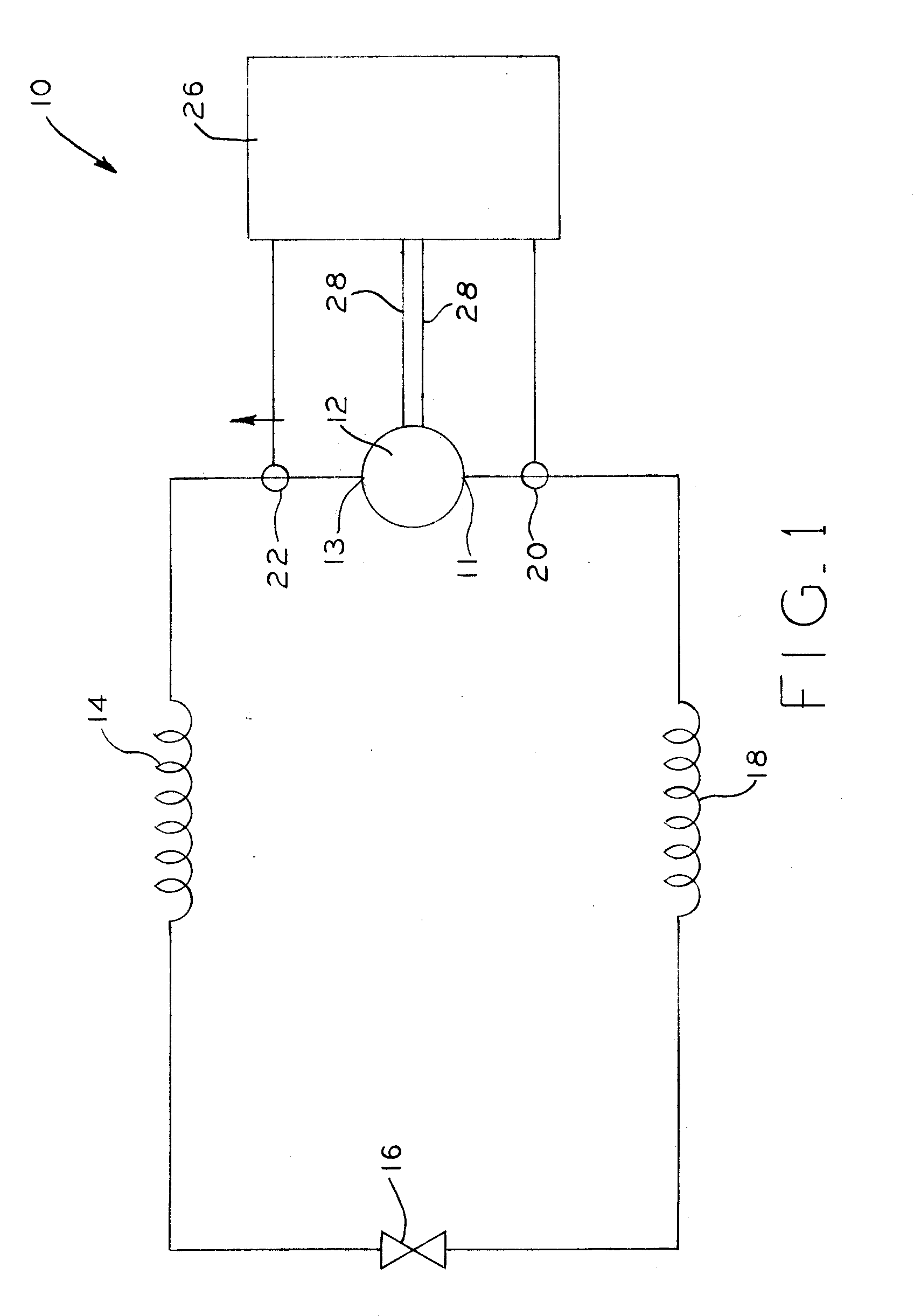
[0018] Referring to FIG. 1, typical refrigeration system 10 includes, in serial order, compressor 12, condenser 14, expansion device 16, and evaporator 18 connected in series by fluid conduits. As is well known in the art, compressor 12 draws a refrigerant or working fluid through compressor inlet 11, compresses the refrigerant, and expels the compressed refrigerant through compressor outlet 13. The refrigerant expelled from compressor 12 is communicated into condenser 14 where thermal energy of the refrigerant is dissipated. Subsequently, the cooled, compressed refrigerant is communicated to expansion device 16 where it is decompressed. The cooled, low-pressure refrigerant is then communicated to evaporator 18 where the refrigerant in evaporator 18 draws heat from an environment surrounding the evaporator. Subsequently, the refrigerant exits evaporator 18 and is communicated to compressor 12 and the cycle described above is repeated.
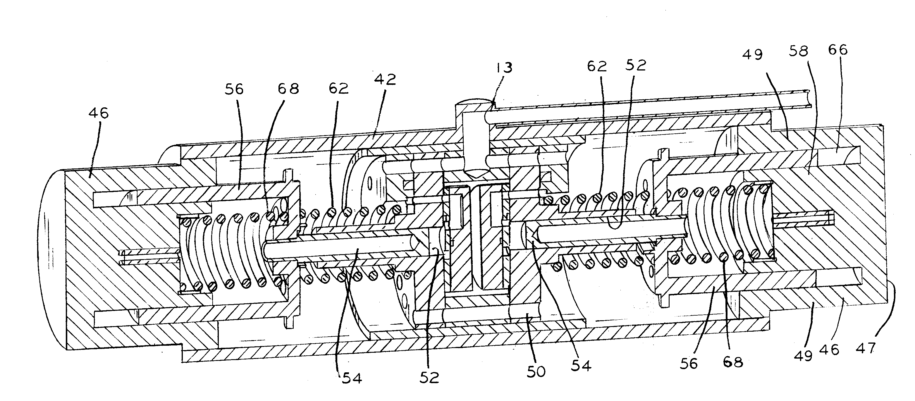
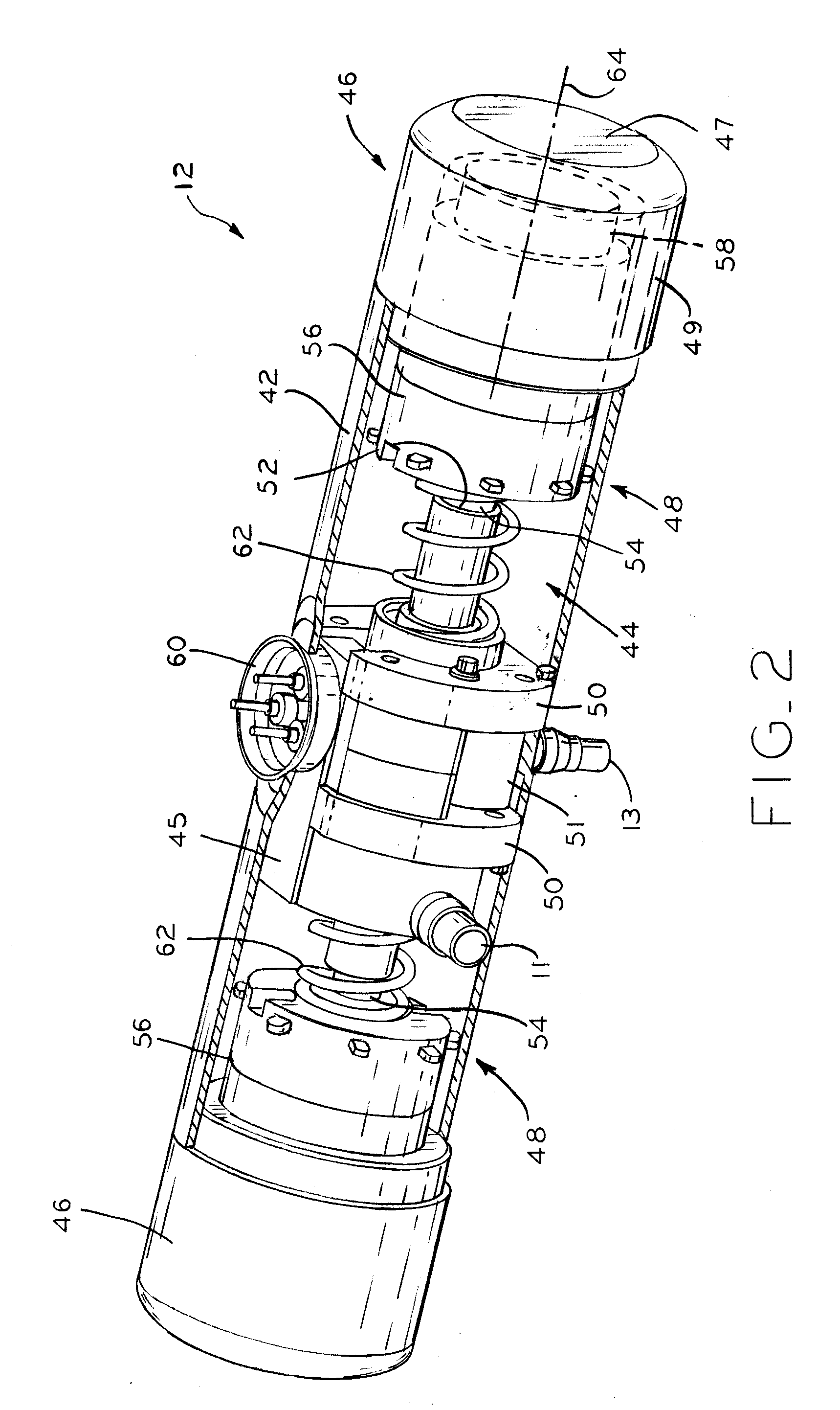
[0019] Referring to FIG. 2, compressor 12, in th...
PUM
 Abstract
Description
Claims
Application Information
 - R&D
- Intellectual Property
- Life Sciences
- Materials
- Tech Scout
- Unparalleled Data Quality
- Higher Quality Content
- 60% Fewer Hallucinations
Browse by: Latest US Patents, China's latest patents, Technical Efficacy Thesaurus, Application Domain, Technology Topic, Popular Technical Reports.
© 2025 PatSnap. All rights reserved.Legal|Privacy policy|Modern Slavery Act Transparency Statement|Sitemap|About US| Contact US: help@patsnap.com


