

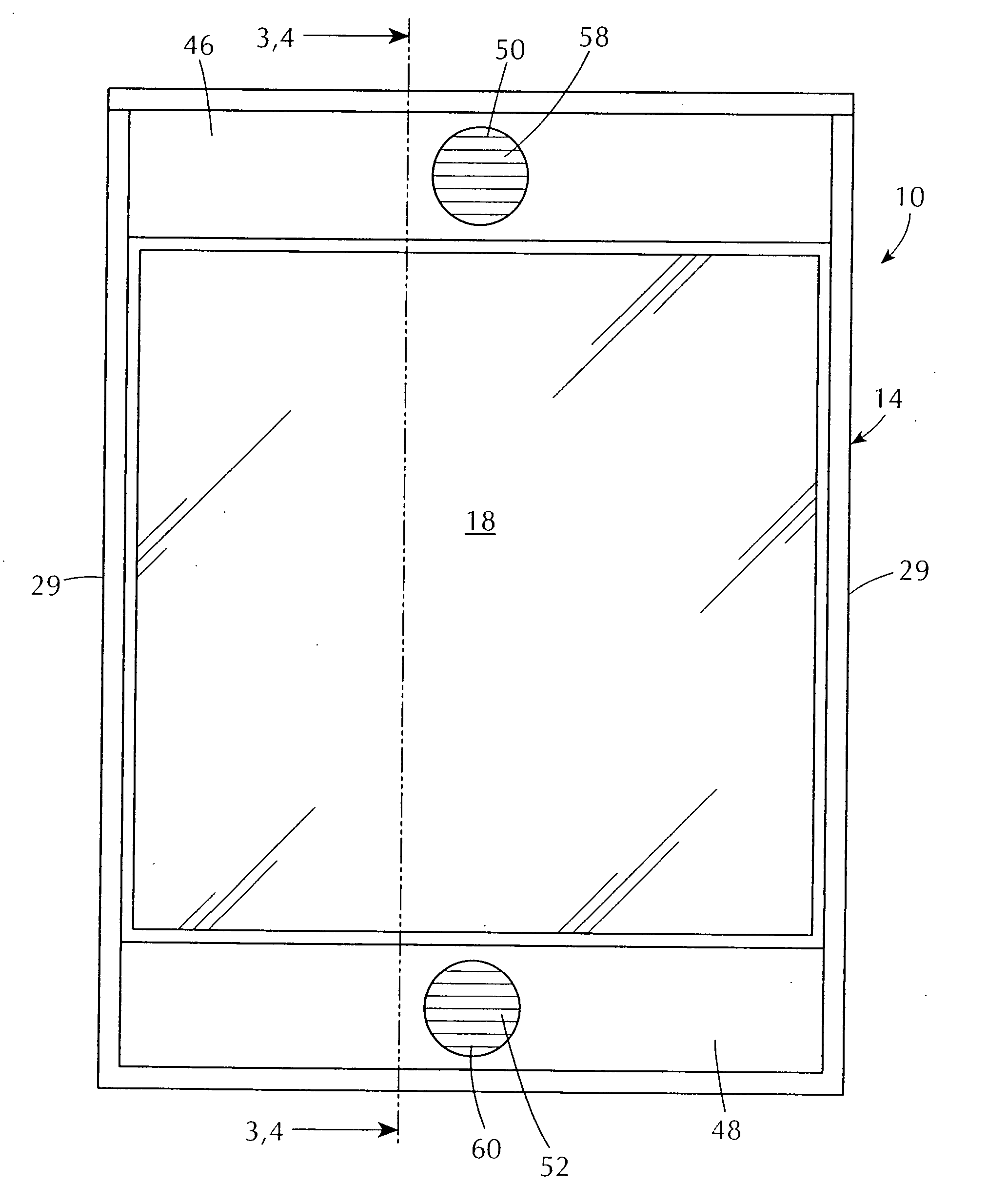
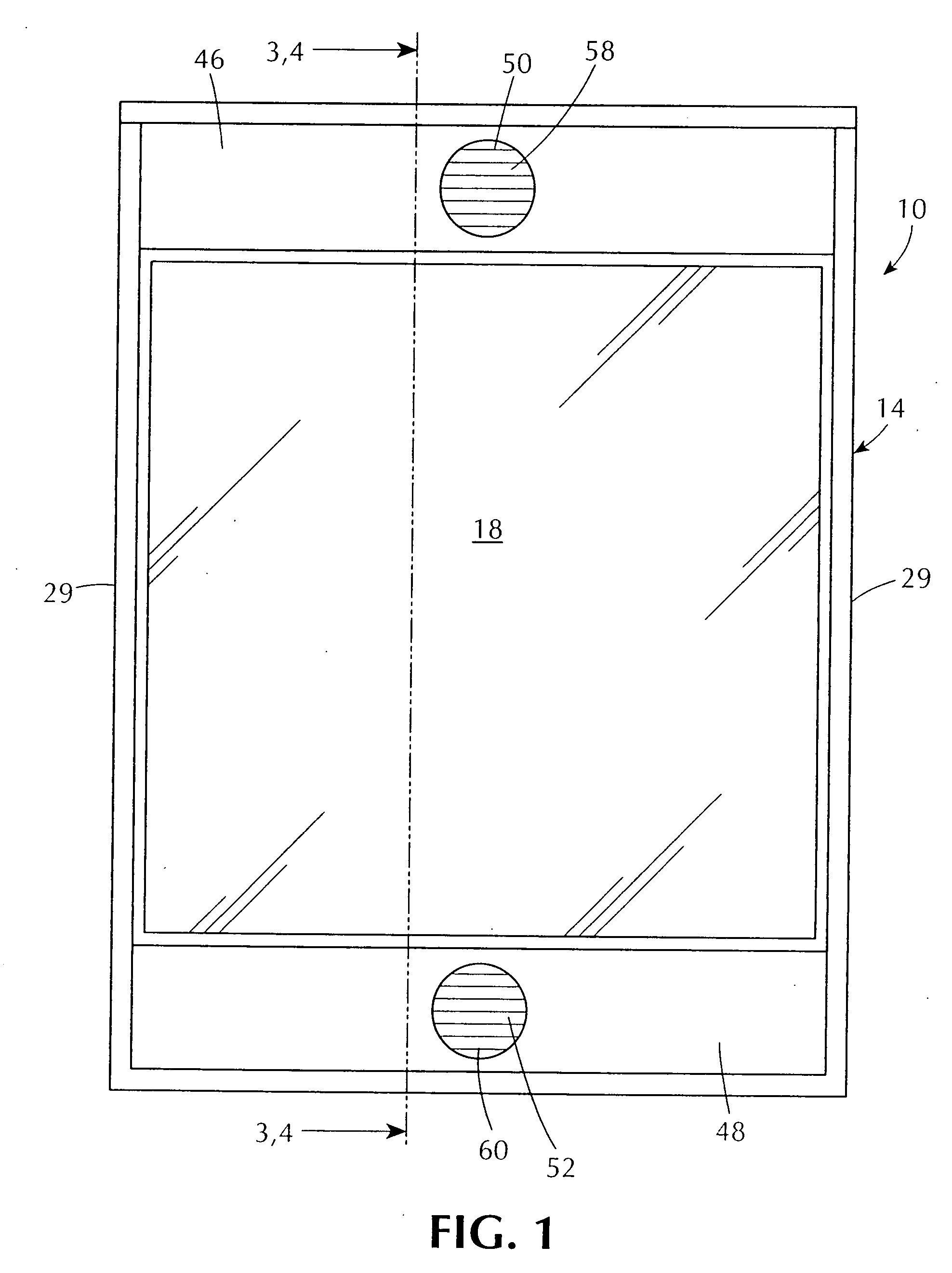
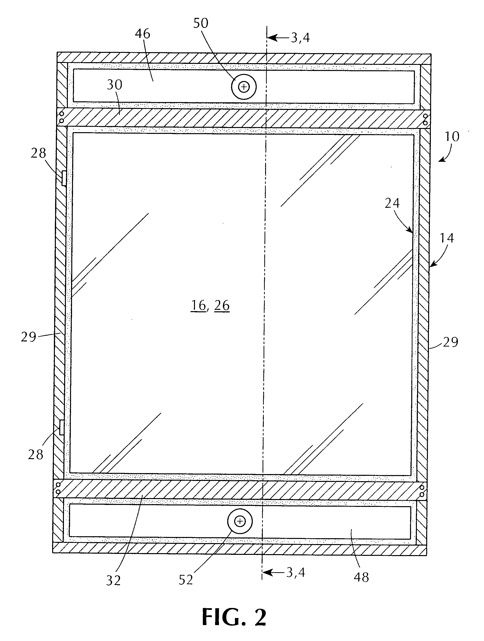
Window for absorbing sunlight heat in warm weather that otherwise would flow uncontrolled therethrough and discharging the sunlight heat to the atmosphere while permitting relatively unobstructed vision therethrough and passing the sunlight heat in cold weather therethrough for thermal warming
- Summary
- Abstract
- Description
- Claims
- Application Information
AI Technical Summary
Benefits of technology
Problems solved by technology
Method used
Image

Examples
Embodiment Construction
[0078] A. General.
[0079] Referring now to the figures, in which like numerals indicate like parts, and particularly to FIGS. 1-4, which are, respectively, a diagrammatic exterior elevational view of the window of the embodiments of the present invention absorbing sunlight heat in warm weather that otherwise would flow uncontrolled therethrough and discharging the sunlight heat to the atmosphere while permitting relatively unobstructed vision therethrough and passing the sunlight heat in cold weather therethrough for thermal warming, a diagrammatic interior elevational view of the window of the embodiments of the present invention absorbing sunlight heat in warm weather that otherwise would flow uncontrolled therethrough and discharging the sunlight heat to the atmosphere while permitting relatively unobstructed vision therethrough and passing the sunlight heat in cold weather therethrough for thermal warming, a diagrammatic cross sectional view taken along LINES 3-3 in FIGS. 1 and ...
PUM
 Abstract
Description
Claims
Application Information