Crowning panel assembly

a technology of crown molding and crown molding, which is applied in the direction of roofs, constructions, building components, etc., can solve the problems of visual distraction, inability to meet the needs of construction, and the cost of standing seam panels compared to other metal panels, so as to reduce the visual impact

Inactive Publication Date: 2007-12-20
RMH TECH LLC
View PDF13 Cites 63 Cited by
  • Summary
  • Abstract
  • Description
  • Claims
  • Application Information

AI Technical Summary

Benefits of technology

[0026]Various refinements exist of the features noted in relation to the fifth aspect of the present invention. Further features may also be incorporated in the fifth aspect of the present invention as well. These refinements and additional features may exist individually or in any combination. Generally, the fifth aspect may be characterized as addressing oil canning or stress wrinkling. T

Problems solved by technology

Standing seam panels are expensive compared to other metal panels, and building surfaces defined by metal panels may be more costly than other types of building surface constructions.
In any case, standing seam panels, as well as possibly other panels, may include a relatively large, planar or flat base section that may tend to exhibit waviness or other surface irregularities after the panel is installed.
This is commonly referred to in the art as “oil canning.” Although oil canning does not necessarily adversely affect the performance of the building surface defined by a plurality of metal panels, many owners and building designers find the aesthetics visually distracting and unacceptable, particularly in view of the premium cost associated with metal panel building surfaces.
This process is expensive

Method used


Image

  • Crowning panel assembly
  • Crowning panel assembly
  • Crowning panel assembly

Examples


Embodiment Construction

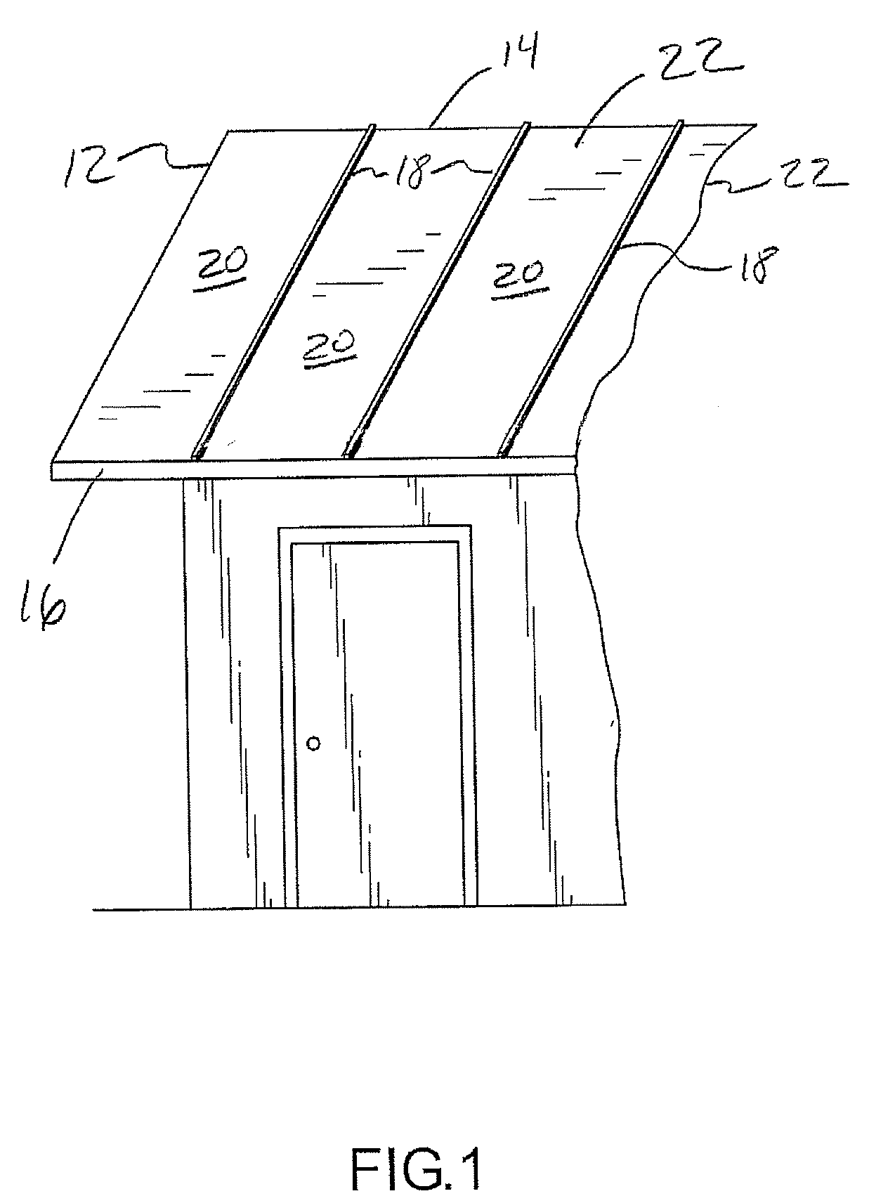
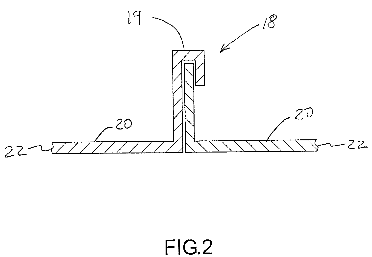
[0042]FIG. 1 illustrates a representative roof 12 of a building. The roof 12 may be of any pitch, but at least generally slopes downwardly from a peak 14 of the roof 12 to an eave 16 of the roof 12. Multiple panels 22 (e.g., metal) are interconnected to define the roof 12. The interconnection of adjacent panels 22 defines a standing seam 18. The length dimension of each standing seam 18 extends from the peak 14 of the roof 12 to the eave 16 of the roof 12, and furthermore the elevation of the various standing seams 18 progressively changes proceeding along their respective length dimensions. Each panel 22 includes a flat, planar base 20 that is disposed between each adjacent pair of standing seams 18. The standing seams 18 may be further characterized as extending at least generally away from the bases 20 that are disposed on each side of the relevant standing seam 18 (FIG. 2, where an upper end 19 of the standing seam 18 is vertically spaced from the adjacent bases 20 of the panels...


PUM


Abstract

A panel assembly (40) that addresses oil canning when installed over a substrate or deck (72) is disclosed. The panel assembly (40) includes a panel (42). The panel (42) includes a first primary panel surface (44) that faces the substrate (72) in the installed configuration, as well as a second primary panel surface (46) that faces away from the substrate (72) in the installed configuration. Another component of the panel assembly (40) is a first structure (60) that is disposed between the panel (42) and the substrate (72). Typically, either a first surface (62) of the first structure (60) is chemically bonded directly to the first primary panel surface (44) such that an interface between the first surface (62) and the first primary panel surface (44) includes a chemical bond, or a second surface (64) is chemically bonded directly to the substrate (72) such that an interface between the second surface (64) and the substrate (72) includes a chemical bond. In any case, the first structure (60) produces a convexity on the second primary panel surface (46) to address oil-canning effects or stress wrinkling of the panel (42).

Description

CROSS-REFERENCE TO RELATED APPLICATIONS[0001]This patent application claims priority under 35 U.S.C. §119(e) to U.S. Provisional Patent Application Ser. No. 60 / 805,275, that was filed on Jun. 20, 2006, that is entitled “CROWNING PANEL ASSEMBLY,” and the entire disclosure of which is hereby incorporated by reference in its entirety herein.FIELD OF THE INVENTION[0002]The present invention generally relates to building surfaces that are susceptible to oil canning or stress wrinkling and, more particularly, to reducing its visual impact on building surfaces.BACKGROUND OF THE INVENTION[0003]Metal panels are being increasingly used to define building surfaces such as roofs and sidewalls. One type of metal panel is a standing seam panel, where the edges of adjacent standing seam panels of the building surface are interconnected in a manner that defines a standing seam. Standing seam panels are expensive compared to other metal panels, and building surfaces defined by metal panels may be mo...

Claims


Application Information

Patent Timeline
IPC IPC(8): E04C1/00
CPCE04C2/08E04D3/30E04D3/366E04D3/364E04D3/363
Inventor HADDOCK, ROBERT M.M.
Owner RMH TECH LLC
Why Eureka
Try Eureka