
Flat wire manufacturing method of manufacturing flat wire for ring gear

a manufacturing method and flat wire technology, applied in the field of flat wire manufacturing, can solve the problems of low dimensional accuracy of flat wire produced by cold rolling process, inability to produce flat wire with high dimensional accuracy, so as to suppress the development of cracks on the side surfaces, the effect of satisfying the dimensional accuracy

Inactive Publication Date: 2007-12-20
KOBE STEEL LTD
View PDF4 Cites 6 Cited by
  • Summary
  • Abstract
  • Description
  • Claims
  • Application Information

AI Technical Summary

Benefits of technology

[0008]Accordingly, it is an object of the present invention to provide a flat wire manufacturing method capable of manufacturing a flat wire for a ring gear satisfactory in both hardness and dimensional accuracy, having a small difference between the hardness of major surfaces and that of side surfaces and not requiring tempering to soften the surface of the flat wire hardened by cold working.
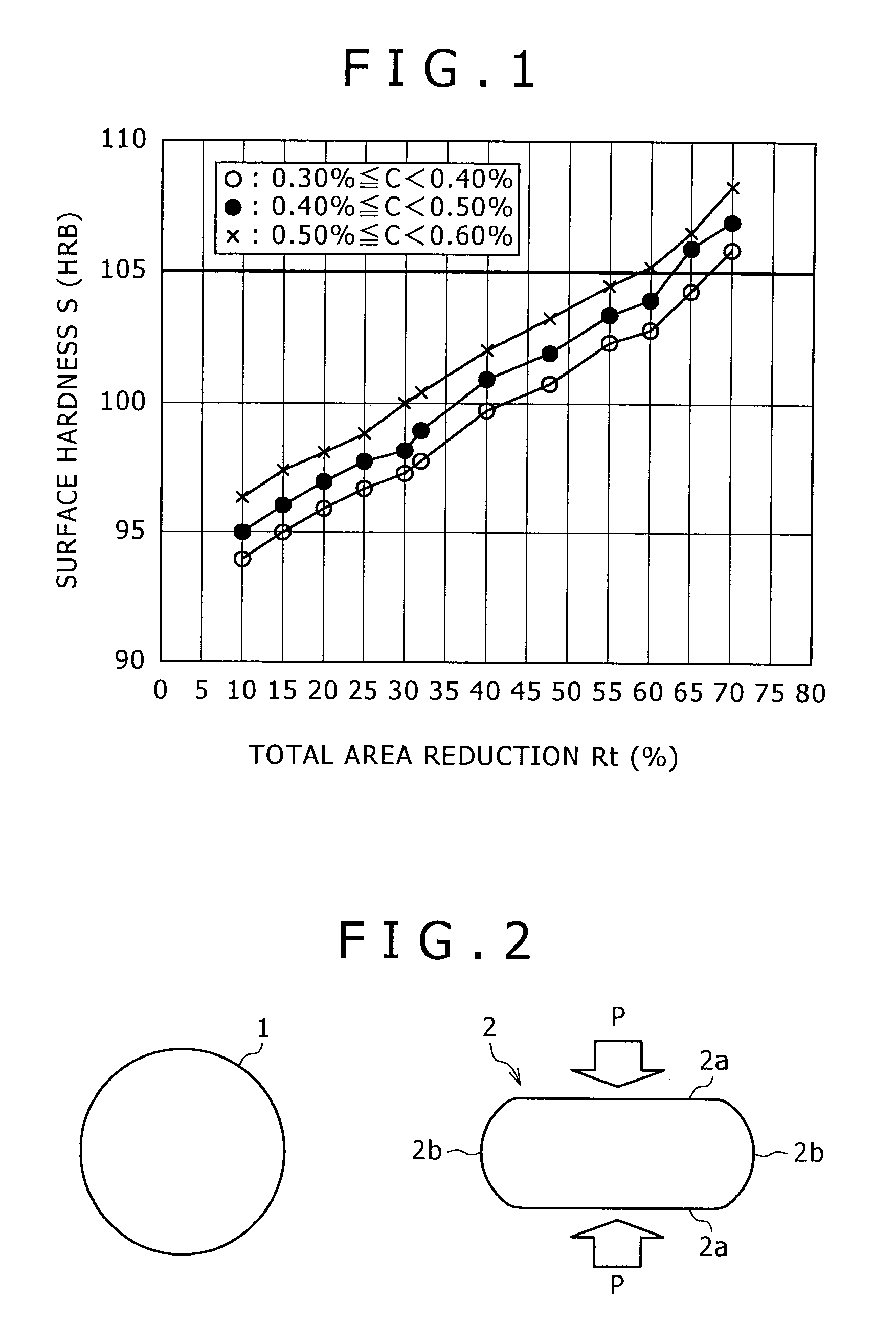
[0013]FIG. 1 is a graph showing the variation of surface hardness S (HRB: Rockwell hardness B) with total area reduction Rt for flat wires formed by processing round steel rods of 15 mm in diameter respectively having different carbon contents by cold working including a flat wire forming process using cold rolling and a flat wire finishing process using a drawing die. The surface hardness S is the mean of the hardnesses of the upper or the lower surface and the side surface of the finished flat wire. It is known from FIG. 1 that the surface hardness S of the flat wire is not dependent on the processing method including cold rolling and cold drawing and is dependent on the total area reduction Rt. The surface hardness S of the finished flat wire for a ring gear needs to be HRB 105 or below in view of workability of the flat wire and avoiding developing cracks in the flat wire when the flat wire is bent in a ring to form a ring gear. It is known from FIG. 1 that a suitable total area reduction Rt in the cold working process is 65% or below for the round steel rod having a carbon content in the range of 0.30 to 0.40%, 60% or below for the round steel rod having a carbon content in the range of 0.40 to 0.50%, and 55% or below for the round steel rod having a carbon content in the range of 0.50 to 0.60%._That is, a total area reduction Rt for the round steel rods having carbon contents in the forgoing ranges needs to be in the range of 55 to 65%. Workability and machinability are important with flat wires for forming parts other than ring gears. Therefore, it is desirable to reduce the hardness of the flat wires for forming parts other than ring gear by processing the round steel rod at a total area reduction of 65% or below by the cold working process. The flat wire finished by die drawing using a drawing die has high dimensional accuracy and ranges in which the widths and thicknesses of thus finished flat wires are distributed can be narrowed. Since the flat wire is finished by die drawing at the last stage of the cold working process, increase in the drawing reduction at which the flat wire is drawn by die drawing can be reduced by the width increasing effect of cold rolling. Since the desired total area reduction is in the range of 55 to 65%, the flat wire has a comparatively low surface hardness. Therefore, the flat wire does not need to be processed by a tempering process for hardness reduction and development of cracks in the side surfaces of the flat wire can be avoided.
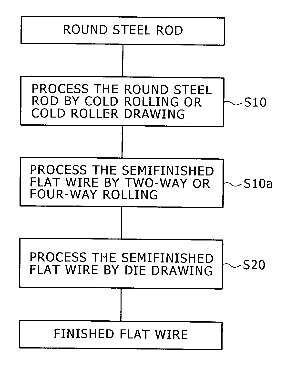
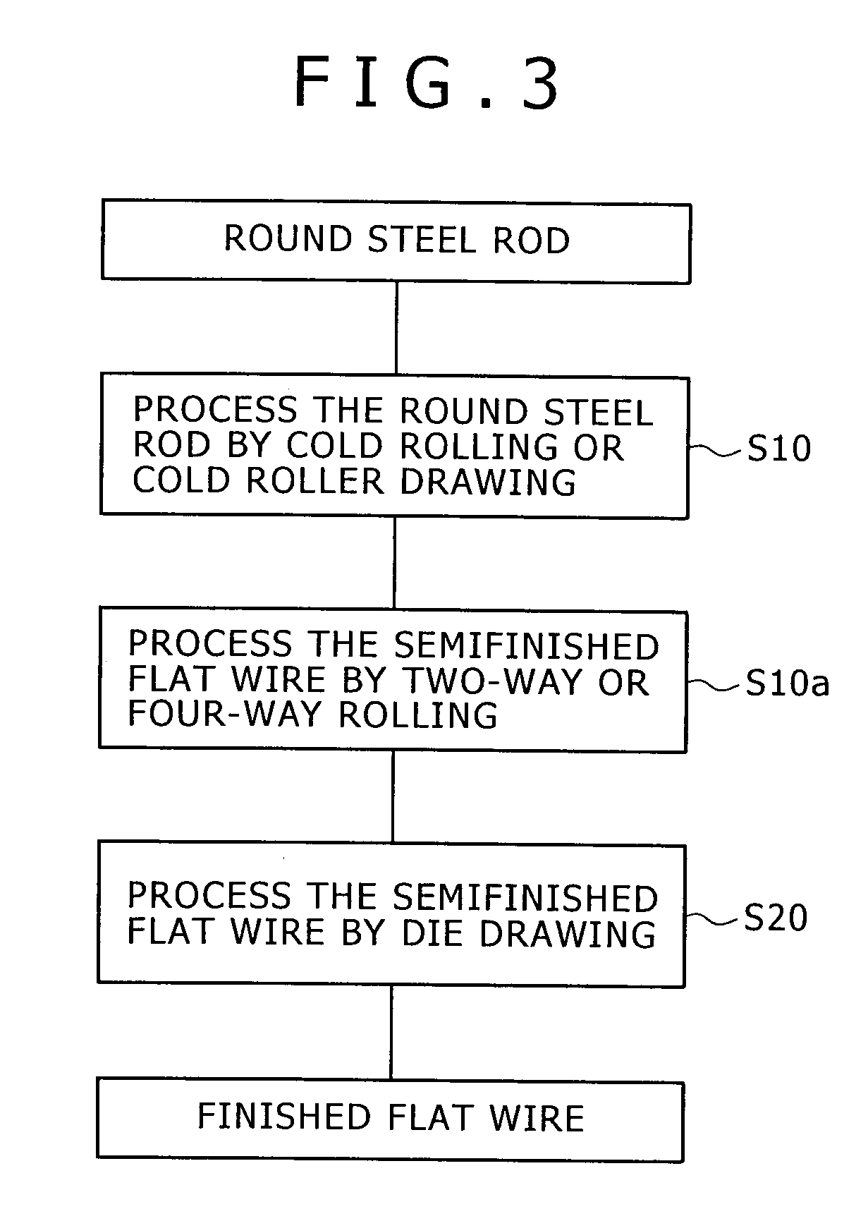
[0015]The flat wire manufacturing method according to the present invention processes a round steel rod by cold rolling or cold roller drawing in the cold working process to form a semifinished flat, and then finishes the semifinished flat wire to obtain a finished flat wire for a ring gear by processing the semifinished flat wire by die drawing using the drawing die, wherein the total area reduction is in the range of 55 to 65% for round steel rods respectively having different carbon contents. The flat wire thus manufactured is satisfactory in dimensional accuracy, has upper and lower surfaces and side surfaces respectively having proper hardnesses distributed in a narrow hardness range, does not need to be processed by a tempering process, and can suppress the development of cracks in the side surfaces.
[0016]When the flat wire manufacturing method includes the two-way rolling step of pressing the side surfaces of the flat wire in two directions parallel to the width of the flat wire at least once or the four-way rolling step of pressing the side surfaces and upper and lower surfaces of the flat wire in four directions at least once to be executed between the flat wire forming step and the flat wire finishing step, the convex side surfaces of the semifinished flat wire can be flattened and hence all the surfaces of the flat wire can be finished in a satisfactory condition.

Problems solved by technology

Although the flat wire manufacturing method that produces a flat wire by processing a round rod only by a cold-rolling process or a hot-rolling process can produce the flat wire at a high productivity because the round rod can be rolled at a high rolling speed, the flat wire manufacturing method cannot produce a flat wire having a high dimensional accuracy.
Flat wires produced by a hot rolling process are inferior in dimensional accuracy to those produced by a cold rolling process and need to be processed by machining processes to remove scales and to a decarburized layer.
When a wide flat wire is produce by processing a round rod at a high working ratio by a cold working process, cracks are liable to be produced in the side surfaces of the flat wire.
It was also found that the flat wire finished only by the cold drawing process mentioned in JP-A 64-27703 has low dimensional accuracy, has major surfaces and side surfaces respectively having different hardnesses, and is unsatisfactory in quality.

Method used


Image

  • Flat wire manufacturing method of manufacturing flat wire for ring gear
  • Flat wire manufacturing method of manufacturing flat wire for ring gear
  • Flat wire manufacturing method of manufacturing flat wire for ring gear

Examples


example 1

[0025]A round steel rod 1 of 15 mm in diameter having a carbon content of 0.48% was used as a workpiece. The workpiece was processed successively by rolling passes shown in FIGS. 4A to 4D. FIGS. 4A to 4E show sectional shapes of the workpiece at the exits of the passes, respectively. The upper and the lower surface 2a and the side surfaces 2b were rolled alternately by changing the rolling directions of the successive passes through 90° A semiconductor finished flat wire 2 of 11 mm in thickness and 14.5 mm in width was obtained by the four cold rolling passes. The semifinished flat wire 2 was finished by cold die drawing using a drawing die to obtain a finished flat wire 2 of 9 mm in thickness and 12 mm in width. The total area reduction of the cold working process was about 40%. Table 1 shows the surface hardnesses (HRB) of flat wires after being processed by the four rolling passes and those of flat wires finished by one drawing pass. In Table 1, “wide surfaces” are upper and lowe...

example 2

[0027]Parameters of the cold working process and total area reduction for working were adjusted to obtain flat wire of 9 mm in thickness and 12 mm width by processing round steel rods having a carbon content of 0.4%. Hardnesses, hardness dispersion, dimensional accuracy and surface quality of flat wires are shown in Table 2. The diameter of the rolling rolls of a two-way rolling mill was 270 mm. Total area reduction was changed by changing the diameters of the round steel rods. In Table 2, a circle in a column of ultimate hardness, namely, hardness of the finished flat wire, indicates a hardness of HRB 100 or below, a circle in a column of ultimate hardness dispersion indicates a difference of HRB 5 or below between the mean of hardnesses of three middle points in the side surface of the finished flat wire and the mean of hardnesses of three middle points in the upper surface (or the lower surface) of the finished flat wire, a circle in a column of dimensional accuracy indicates tha...


PUM

PropertyMeasurementUnit
diameteraaaaaaaaaa
thicknessaaaaaaaaaa
thicknessaaaaaaaaaa

Abstract

A round steel rod having a carbon content between 0.30 and 0.60% is processed by a cold working process to form a flat wire for forming a ring gear. The cold working process forms a semifinished flat wire by at least one cold rolling or cold roller drawing step and at least one two-way or four-way rolling step. The semifinished flat wire is processed by die drawing using a drawing die to obtain a finished flat wire in a last stage of the cold working process. The cold working process reduces the round steel rod at a total area reduction of 65% or below.

Description

BACKGROUND OF THE INVENTION[0001]1. Field of the Invention[0002]The present invention relates to a flat wire manufacturing method of manufacturing a flat wire having high dimensional accuracy for forming a ring gear by processing a round rod by cold working without requiring tempering to soften the surface of the flat wire hardened by cold working.[0003]2. Description of the Related Art[0004]There are various flat wire manufacturing methods of manufacturing flat wires for forming ring gears and spiral wires. Those methods include a flat wire manufacturing method of manufacturing a flat wire by die drawing a hot-rolled flat wire, a flat wire manufacturing method of manufacturing a flat wire by die drawing a hot-rolled round rod, a flat wire manufacturing method of manufacturing a flat wire by cold-drawing a hot-rolled round rod and a flat wire manufacturing method of manufacturing a flat wire by hot-rolling a hot-rolled round rod.[0005]Although the flat wire manufacturing method that...

Claims


Application Information

Patent Timeline
Patent Type & Authority Applications(United States)
IPC IPC(8): B21C1/00B21C37/04B21F21/00B21F99/00
CPCB21C1/00B21B1/16
Inventor KUSHIDA, HITOSHIISHIGAMI, OSAMUOKOCHI, NORIOMIYAZAKI, SHOJI
Owner KOBE STEEL LTD
Learn More