Flap drive

Active Publication Date: 2007-12-20
STABILUS
View PDF19 Cites 17 Cited by
  • Summary
  • Abstract
  • Description
  • Claims
  • Application Information

AI Technical Summary

Benefits of technology

[0006] It is the object of the invention to provide a flap drive of the aforementioned type which, with a simple

Problems solved by technology

As not only a specific actuating force has to be applied, therefore, but also a

Method used


Image

  • Flap drive
  • Flap drive
  • Flap drive

Examples


Embodiment Construction

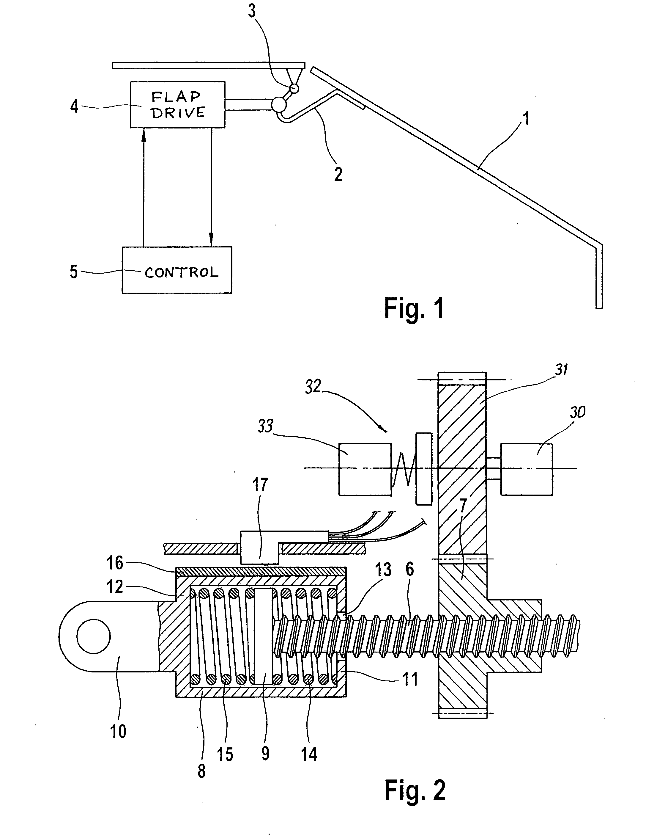
[0037] A flap 1 is shown in FIG. 1, which is a tailgate of a motor vehicle and which is pivotable via a link part 2 about a pivot axis 3. The pivot axis 3 extends along an aperture of the bodywork of the motor vehicle on the roof side which may be closed by the flap 1.

[0038] The link part 2 may be impinged upon by a linearly movable element of a flap drive 4 at a radial distance from the pivot axis 3, transversely to the extension of the pivot axis 3.

[0039] The flap 1 pivoted out of its closed position into an open position remains in this open position, held by a holding device, as long as the holding device is not releasably activated by an electrical control device 5.

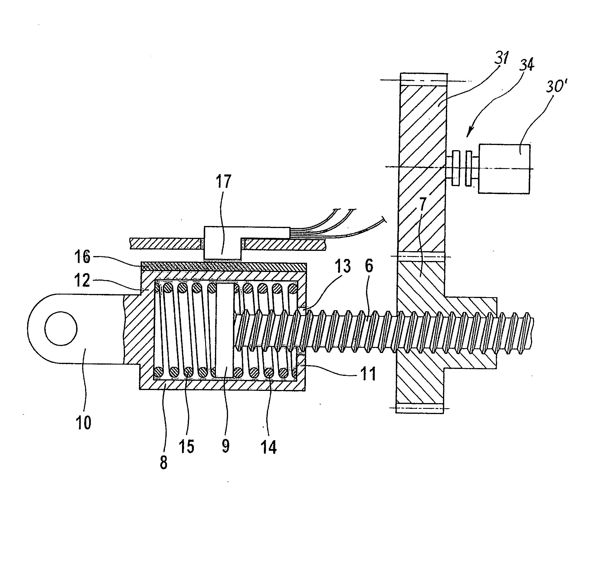
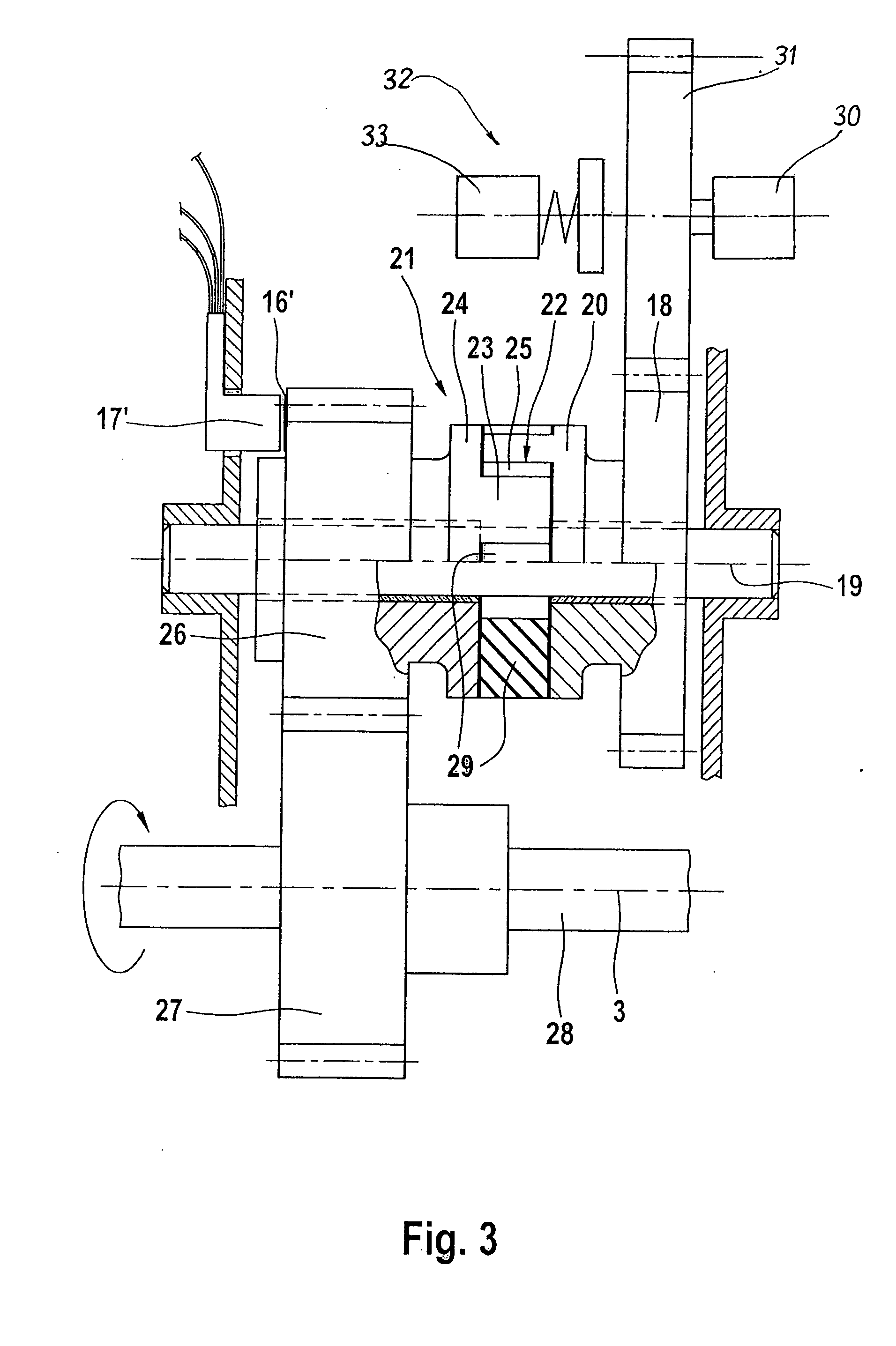
[0040] The flap drive 4 shown in FIG. 2 includes a threaded spindle 6 forming a linearly movable drive part and secured against rotation, which is driven in a linearly movable manner by a spindle nut 7 which may be rotatably driven by an electric motor 30 and a drive pinion 31.

[0041] The threaded spindle 6 projec...


PUM


Abstract

A drive train for a pivotable flap of a motor vehicle includes a holding device which can hold the flap in at least one open position, a first element which can be driven by a drive motor, and a second element connected to the pivotable flap to pivot the flap in response to movement of the first element. When the second element is moved along a path of motion relative to the first element counter to a specific spring force, a sensor generates a signal indicating relative motion of the elements, and a control device releases the holding device in response to the signal, whereby the flap can be moved manually by applying a force counter to the spring force.

Description

BACKGROUND OF THE INVENTION [0001] 1. Field of the Invention [0002] The invention relates to a flap drive, in particular for a flap of a motor vehicle, with a drive train including a drive motor and a plurality of elements leading to a component of the flap which is pivotable about a pivot axis. The flap can be held in one or more open positions by a holding device, and when acted upon by manual force is at least substantially freely movable in the opening and / or closing direction. [0003] 2. Description of the Related Art [0004] With such flap drives, it is necessary to hold the flap, without expending energy, in an intermediate position or in the fully open position against its own weight or against excessive forces of the counter balancing used for the flap, a manual mobility of the flap always having to be provided. [0005] With such a flap drive it is known that an application of manual force on the flap is detected by a force sensor or torque sensor. SUMMARY OF THE INVENTION [00...

Claims


Application Information

Patent Timeline
IPC IPC(8): F16H25/00
CPCE05F5/00E05F15/70E05Y2201/26E05Y2201/462E05Y2400/44E05Y2600/458E05Y2800/112E05Y2900/546E05Y2201/492E05Y2201/216E05Y2201/474E05Y2600/13E05Y2800/21E05Y2800/00E05Y2800/234E05Y2800/232E05Y2201/438E05Y2800/40Y10T74/18032E05F15/622E05Y2201/21E05Y2400/552
Inventor RITTER, ANDREAS
Owner STABILUS
Why Eureka
Try Eureka