
Turner assembly for a web-fed rotary press

a technology of rotary presses and turners, which is applied in the direction of printing presses, thin material handling, printing, etc., can solve the problems of limited flexibility of previously known practical, complicated and expensive, and achieve the effect of reducing investment costs and high flexibility

Inactive Publication Date: 2007-12-20
MANROLANAD AG
View PDF11 Cites 2 Cited by
  • Summary
  • Abstract
  • Description
  • Claims
  • Application Information

AI Technical Summary

Benefits of technology

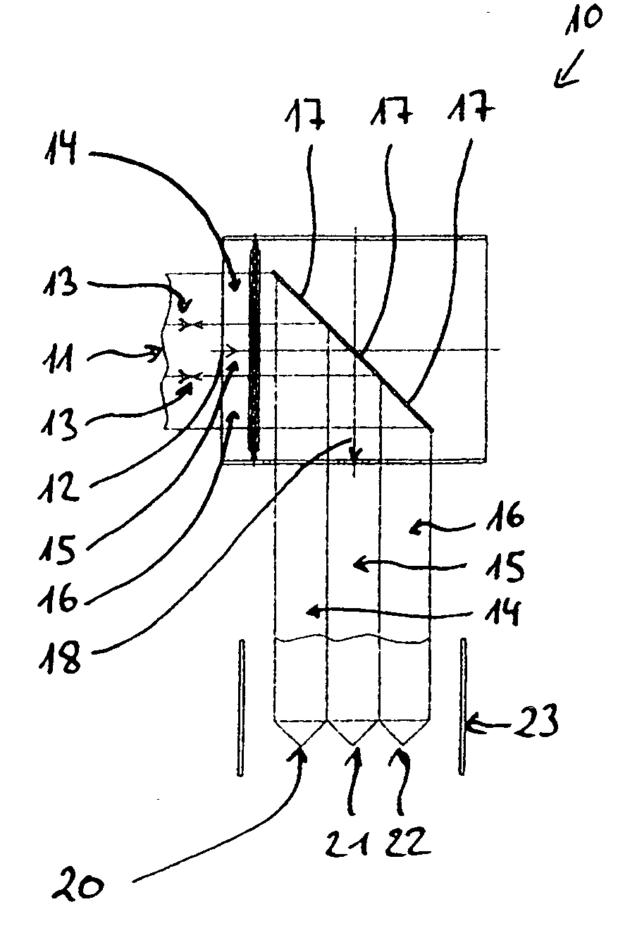
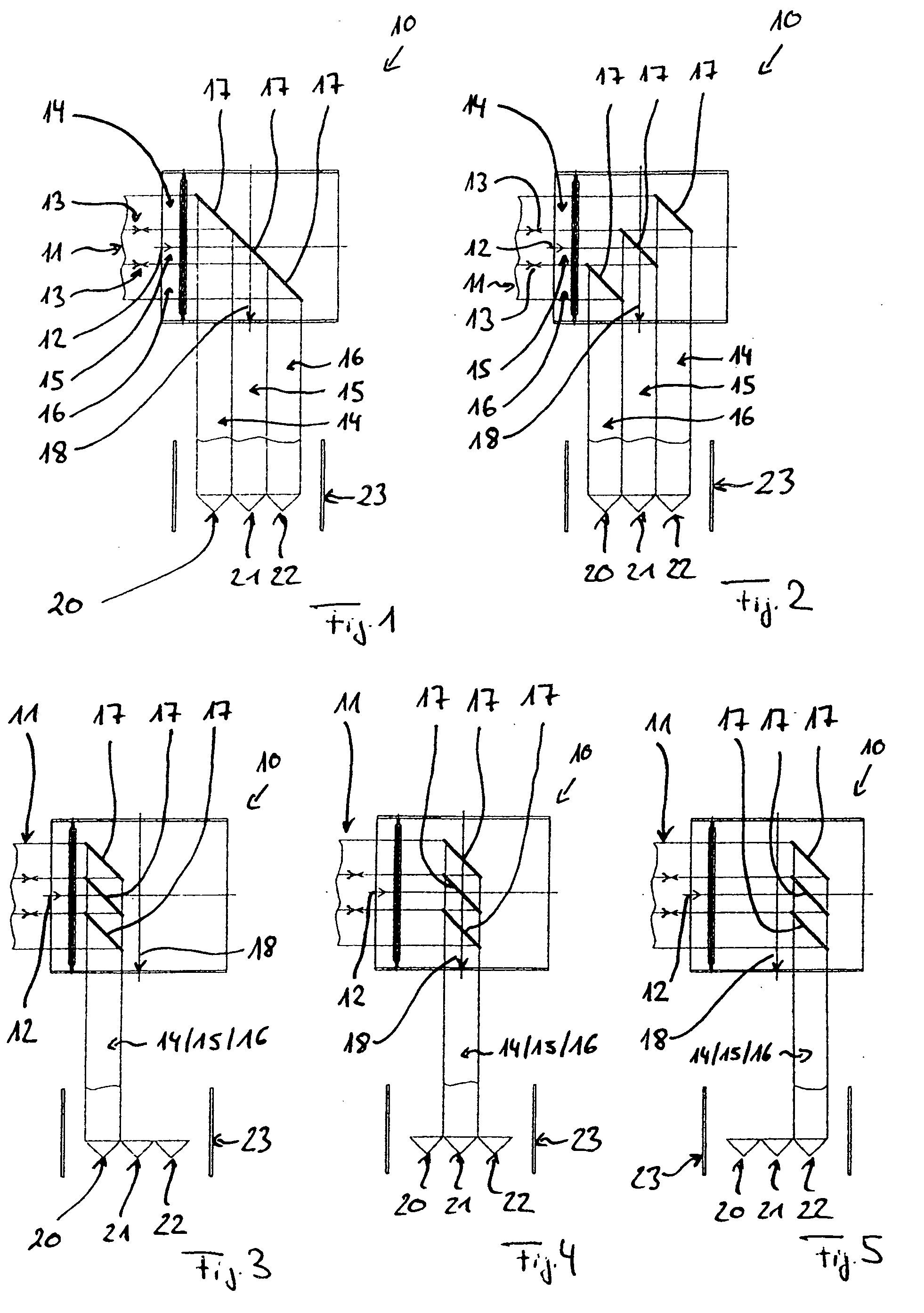
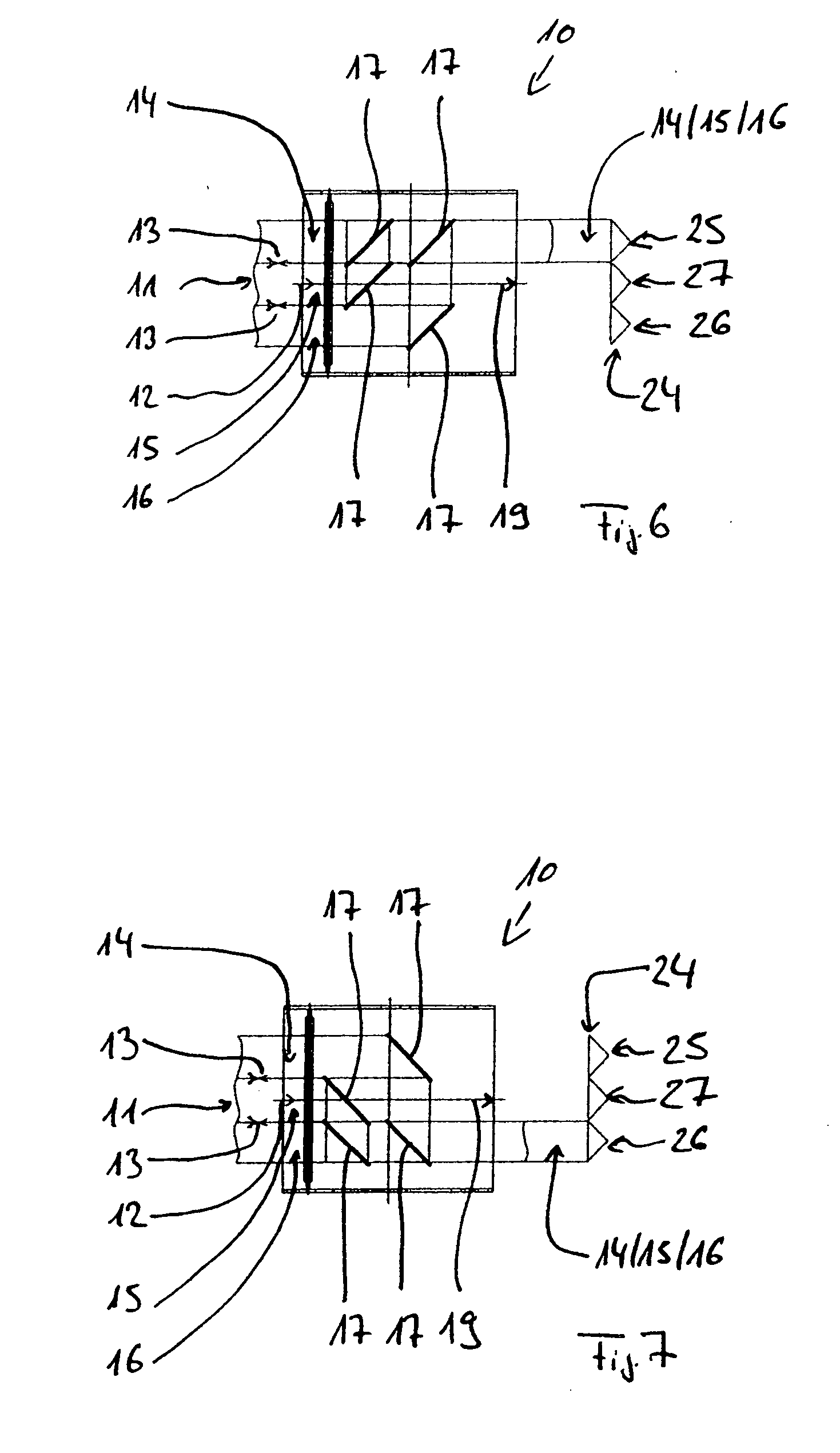
[0007] The turner assembly of the present invention is distinguished by a high degree of flexibility. For example, after being turned and deflected, a partial web may be selectively fed to one of several folder superstructures or formers with the turner assembly of the invention. To this end, at least one turner bar, which can be moved in the entry direction, is assigned to each partial web. Depending on the position of the corresponding turner bars in relation to the respective partial webs, the latter are selectively fed to one of several formers or folder superstructures. This flexibility is present both when the exit direction is displaced about 90° relative to the entry direction of the partial webs and when the exit direction of the partial webs is the same as the entry direction. Each partial web can be individually turned and deflected independently of other partial webs and then selectively fed to one of several folder superstructures or formers.
[0008] The turner assembly of the present invention thus provides full flexibility and mixability of the partial webs to be turned on the turner assembly with respect to folder superstructures or formers, to which the partial webs turned and deflected on the turner assembly are fed. This allows a reduction in the required number of turner assemblies compared to the prior art and thus reduces investment costs for web-fed rotary presses.

Problems solved by technology

As a result of this limited flexibility of previously known practical turner assemblies, after a partial web has been turned and deflected and it is to be selectively fed to one of several folder superstructures or formers, several turner assemblies are required.
This is complicated and expensive.

Method used


Image

  • Turner assembly for a web-fed rotary press
  • Turner assembly for a web-fed rotary press
  • Turner assembly for a web-fed rotary press

Examples


Embodiment Construction

[0019] The present invention will now be described with reference to FIGS. 1 to 7, which illustrate an example of a turner assembly 10, to which a web 11 of a web-like printed material can be fed in an entry direction 12. In the specific embodiment shown here, the web 11 can be cut into three partial webs 14, 15, and 16 by two schematically indicated slitters 13, and the partial webs 14, 15, and 16 can be turned and deflected on turner bars 17 of the turner assembly 10. In FIGS. 1 to 5, the exit direction 18 of the partial webs 14 to 16 from the turner assembly 10 is displaced by 90° relative to the entry direction 12, i.e., the exit direction is approximately perpendicular to the entry direction. In FIGS. 6 and 7, on the other hand, the exit direction 19 is the same as the entry direction 12.

[0020] In accordance with the present invention, at least one turner bar 17 is assigned to each partial web 14, 15, and 16. Each of the turner bars 17 can be individually moved in the entry di...


PUM

PropertyMeasurementUnit
Angleaaaaaaaaaa

Abstract

A turner assembly for a web-fed rotary press includes a plurality of turner bars, wherein at least one web of a web-like printed material is introduced into the turner assembly in an entry direction. Slitters arranged upstream of the turner bars in the entry direction of the printed material cut the web into partial webs which are turned and deflected on the turner bars such that turned partial webs are led out of the turner assembly in an exit direction. At least one turner bar is assigned to each partial web and is individually moved in the entry direction such that each of the partial webs are fed to one of several formers or folder superstructures, depending on the position of the corresponding turner bar or each corresponding turner bar.

Description

BACKGROUND OF THE INVENTION [0001] 1. Field of the Invention [0002] The invention concerns a turner assembly for a web-fed rotary press configured to receive a web of a web-like printed material in an entry direction, the turner assembly having a plurality of turner bars and slitters arranged upstream of the turner bars in the entry direction of the printed material, the slitters being configured to cut the web into partial webs, and the partial webs can be turned and deflected on the turner bars such that turned partial webs are led out of the turner assembly in an exit direction. [0003] 2. Description of the Related Art [0004] A turner assembly of a web-fed rotary press receives a web of a web-like printed material, which is usually fed to the turner assembly in several planes arranged one above the other, and which is separated into partial webs and then turned and deflected on the turner assembly. During a turning and deflection by about 90° relative to an axis of the turner ass...

Claims


Application Information

Patent Timeline
IPC IPC(8): B41F13/54
CPCB41F13/06B65H2301/4148B65H23/32B41F13/56
Inventor BOTSCH, MARKUSMENZINGER, STEFANWAGNER, ERICH
Owner MANROLANAD AG
Learn More