
Pad structure and method of testing

Active Publication Date: 2007-12-20
TAIWAN SEMICON MFG CO LTD
View PDF6 Cites 12 Cited by
  • Summary
  • Abstract
  • Description
  • Claims
  • Application Information

AI Technical Summary

Benefits of technology

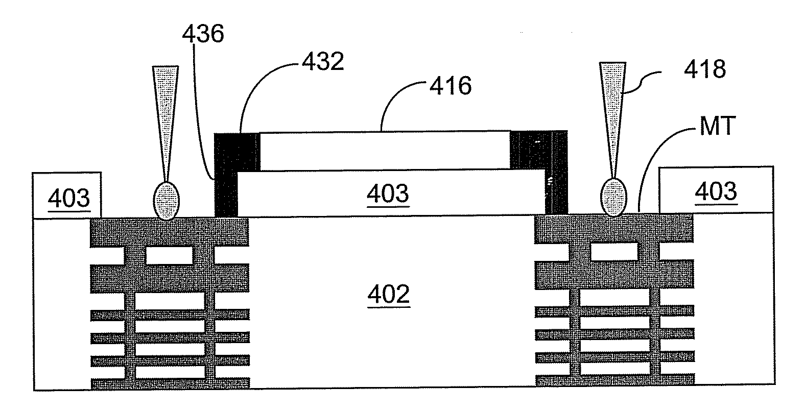
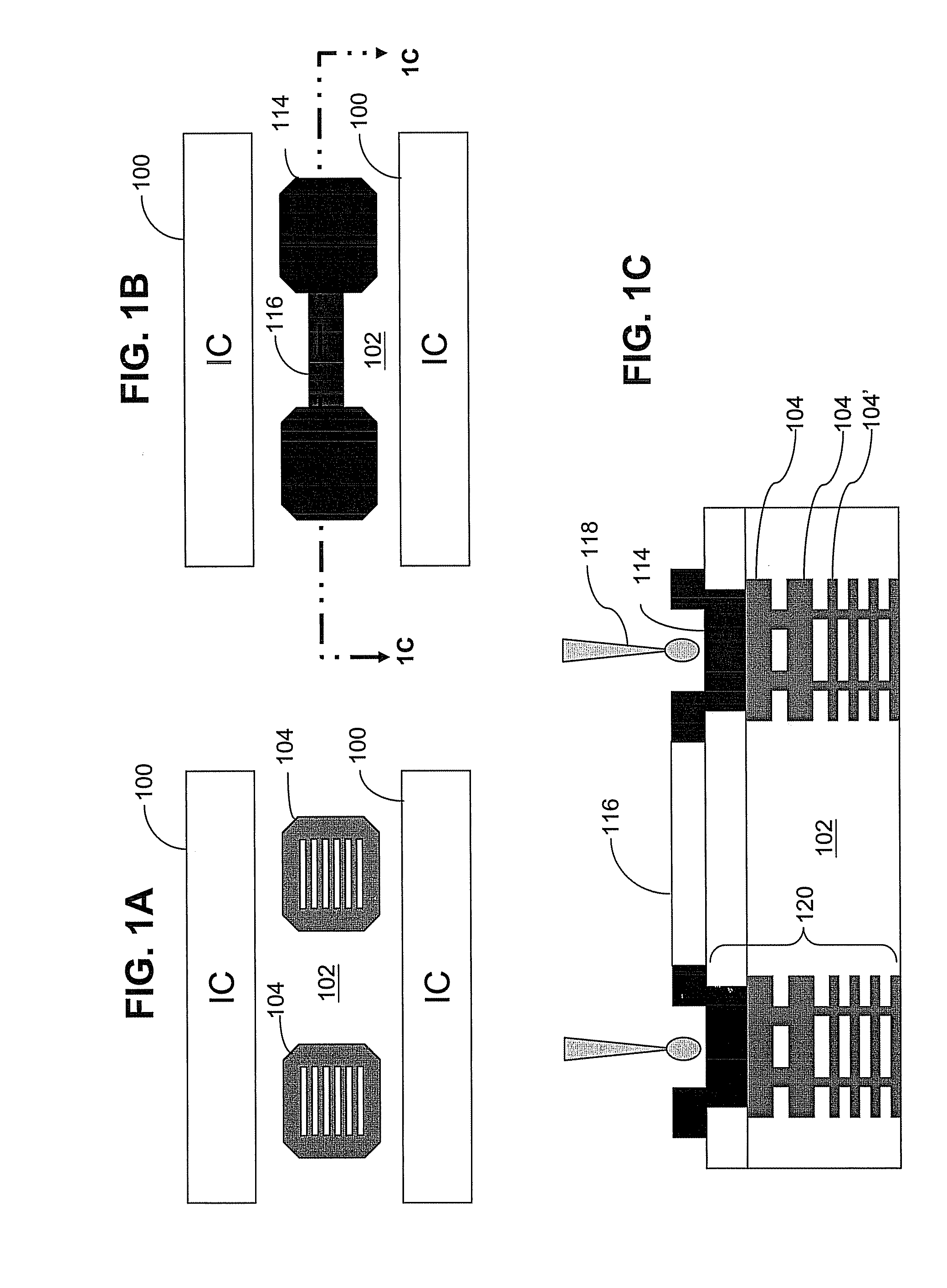
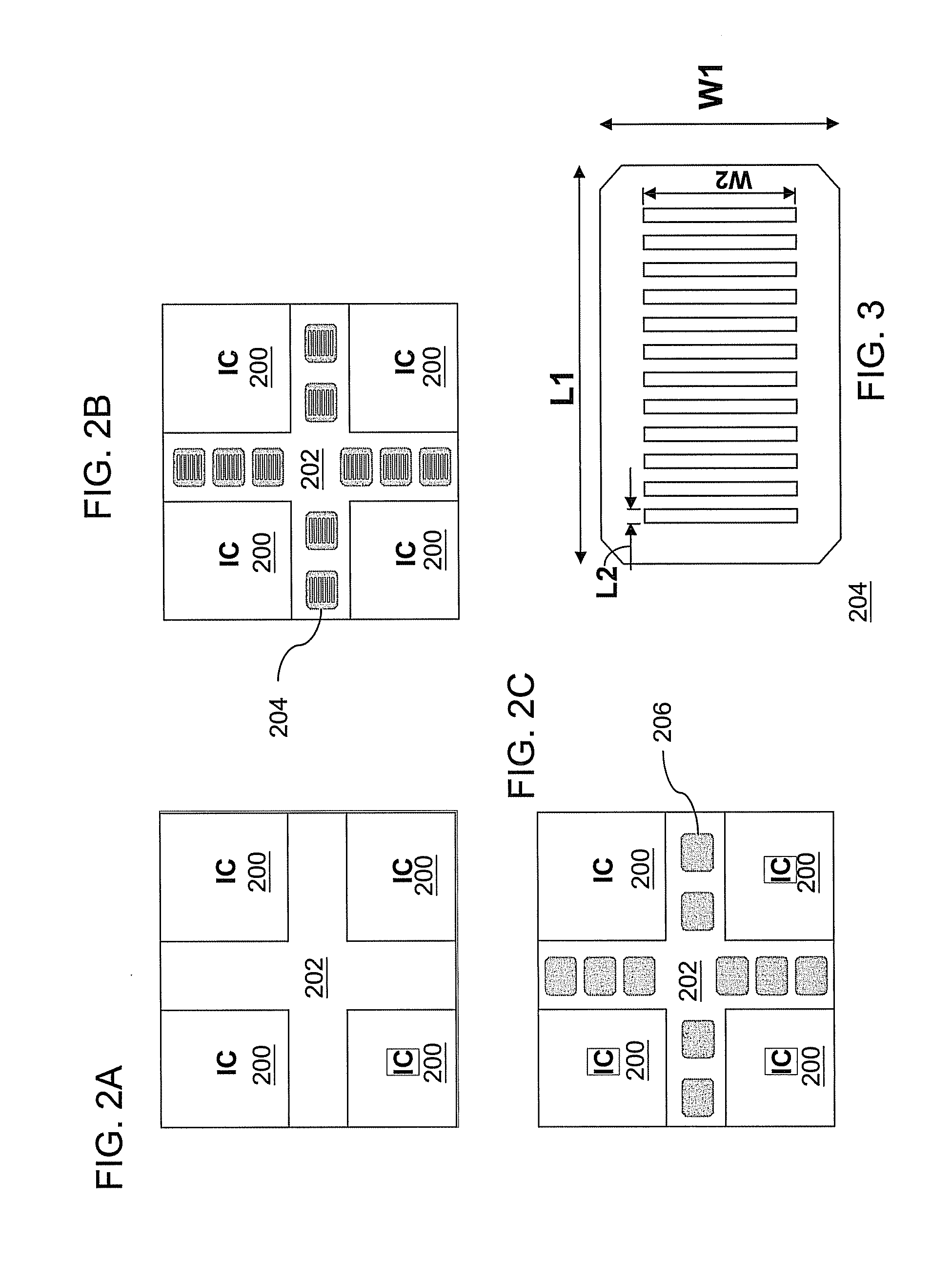
[0012]In some embodiments, an interconnect structure comprises a plurality of dielectric layers having aligned process control monitor (PCM) pads in at least one scribe line. A conductive structure above a topmost one of the PCM pads electrically connects the topmost PCM pad to a device under test above a level of the topmost PCM pad. The conductive structure is sized and shaped so as to leave a majority portion of the topmost PCM pad exposed for access by a circuit probe.
[0013]In some embodiments, a wafer, comprises a substrate having a plurality of integrated circuits formed above the substrate, and at least one scribe line between two of the integrated circuits. A plurality of dielectric layers are formed in the at least one scribe line having aligned process control monitor (PCM) pads formed therein. A co

Problems solved by technology

Conventional multi-level interconnect structures have been susceptible to failure due to cracking when the PCM pad 120 is cut by a die saw.
This problem becomes more acute when low-k dielectric materials (including extreme low k, ELK and ultra low k, ULK) are used for the ILD material, because low-k dielectric materials are more brittle than high k dielectrics.
Cracking is severe in the aluminum layer.

Method used


Image

  • Pad structure and method of testing
  • Pad structure and method of testing
  • Pad structure and method of testing

Examples


Embodiment Construction

[0026]This description of the exemplary embodiments is intended to be read in connection with the accompanying drawings, which are to be considered part of the entire written description. In the description, relative terms such as “lower,”“upper,”“horizontal,”“vertical,”, “above,”“below,”“up,”“down,”“top” and “bottom” as well as derivative thereof (e.g., “horizontally,”“downwardly,”“upwardly,” etc.) should be construed to refer to the orientation as then described or as shown in the drawing under discussion. These relative terms are for convenience of description and do not require that the apparatus be constructed or operated in a particular orientation. Terms concerning attachments, coupling and the like, such as “connected” and “interconnected,” refer to a relationship wherein structures are secured or attached to one another either directly or indirectly through intervening structures, as well as both movable or rigid attachments or relationships, unless expressly described othe...


PUM


Abstract

An interconnect structure includes: a plurality of dielectric layers having aligned process control monitor (PCM) pads, and a conductive structure above a topmost one of the PCM pads. The conductive structure electrically connects the topmost PCM pad to a device under test above a level of the topmost PCM pad. The conductive structure is sized and shaped so as to leave a majority portion of the topmost PCM pad exposed for access by a test probe.

Description

[0001]This application claims the benefit of U.S. Provisional Patent Application No. 60 / 805,270, filed Jun. 20, 2006, which is incorporated by reference herein in its entirety.FIELD OF THE INVENTION[0002]The present invention relates to semiconductor devices and fabrication techniques generally, and more particularly relates to interconnect structures and test methods.BACKGROUND[0003]In order to achieve high-integration and high-speed, dimensions of semiconductor integrated circuits have been reduced, and various materials and techniques have been proposed and used during fabrication. For example, dual damascene technology and copper conductors are applied to reduce resistances and resistance-capacitance (RC) delay of interconnect structures in ICs. As ICs are made smaller, and the distance between adjacent lines is reduced, low-k (low dielectric constant) dielectric materials are used in advanced copper interconnect technology to reduce these delays.[0004]Interconnect structures of...

Claims


Application Information

Patent Timeline
IPC IPC(8): H01L23/52
CPCH01L22/32H01L2224/02166H01L22/34
Inventor CHEN, HSIEN-WEI
Owner TAIWAN SEMICON MFG CO LTD
Learn More