Systems and methods for dynamic mode-driven link management

a dynamic mode and link management technology, applied in the field of communication networks, can solve the problems of inability to increase the bandwidth available to the network, overly complex network addressing schemes and routing tables, and additional delays in the network

Inactive Publication Date: 2007-12-20
HARRIS CORP
View PDF99 Cites 29 Cited by
  • Summary
  • Abstract
  • Description
  • Claims
  • Application Information

AI Technical Summary

Benefits of technology

[0031]Certain embodiments provide a network communication system providing quality of service. The system includes a communication manager controlling a flow of messages in a network. The system also includes a message management rules module applying one or more rules to affect the flow of the messages in the network. The one or more rules are configured by a mode. The mode is defined in a profile and includes one or more parameters related to the one or more rules.

Problems solved by technology

Due to the diversity of the types of links and nodes, among other reasons, tactical networks often have overly complex network addressing schemes and routing tables.
These constraints may be due to either the demand for bandwidth exceeding the supply, and / or the available communications technology not supplying enough bandwidth to meet the user's needs.
This may cause additional delays.
In many instances the bandwidth available to a network cannot be increased.
For example, the bandwidth available over a satellite communications link may be fixed and cannot effectively be increased without deploying another satellite.
Networks can be highly volatile and available bandwidth can change dramatically and without notice.
In addition to bandwidth constraints, tactical data networks may experience high latency.
Another characteristic common to many tactical data networks is data loss.
Data may be lost due to a variety of reasons.
For example, a node with data to send may be damaged or destroyed.
This may occur because, for example, the node has moved out of range, the communication's link is obstructed, and / or the node is being jammed.
Data may be lost because the destination node is not able to receive it and intermediate nodes lack sufficient capacity to buffer the data until the destination node becomes available.
Additionally, intermediate nodes may not buffer the data at all, instead leaving it to the sending node to determine if the data ever actually arrived at the destination.
Often, applications in a tactical data network are unaware of and / or do not account for the particular characteristics of the network.
Applications which do not take into consideration the specific characteristics of the underlying communications network may behave in ways that actually exacerbate problems.
Certain protocols do not work well over tactical data networks.
For example, a protocol such as TCP may not function well over a radio-based tactical network because of the high loss rates and latency such a network may encounter.
High latency and loss may result in TCP hitting time outs and not being able to send much, if any, meaningful data over such a network.
Thus, the network provides no guarantees that any given piece of data will reach its destination in a timely manner, or at all.
Additionally, no guarantees are made that data will arrive in the order sent or even without transmission errors changing one or more bits in the data.
Delays in data delivery in such a case may result in irritating gaps in communication and / or dead silence, for example.
IntServ does not scale well because of the large amount of state information that must be maintained at every node and the overhead associated with setting up such connections.
Existing QoS systems cannot provide QoS based on message content at the transport layer.
Current network link designs are tedious and difficult.
Dynamic, “on-the-fly” changes to network link designs are also difficult.
Implementations often collapse or combine various layers of the OSI network model.
The network is static, and even minor changes require considerable rework.

Method used


Image

  • Systems and methods for dynamic mode-driven link management
  • Systems and methods for dynamic mode-driven link management
  • Systems and methods for dynamic mode-driven link management

Examples


Embodiment Construction

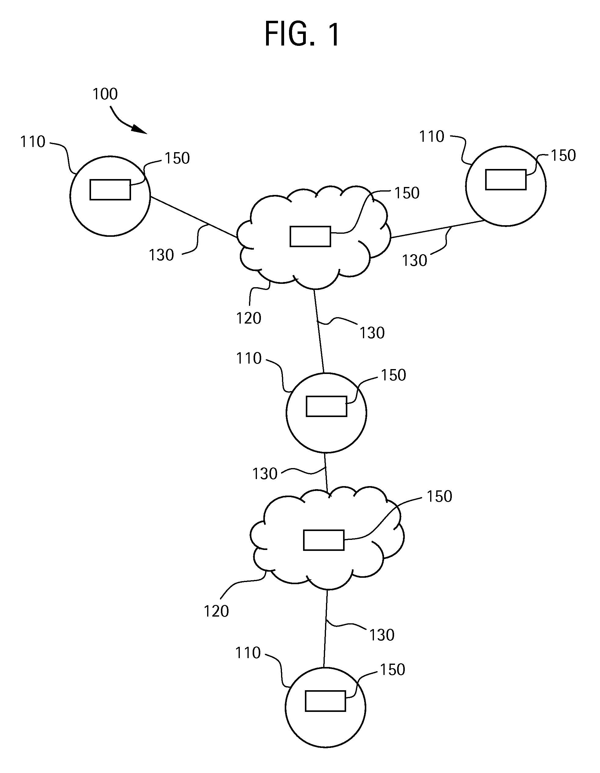
[0041]FIG. 1 illustrates a tactical communications network environment 100 operating with an embodiment of the presently described technology. The network environment 100 includes a plurality of communication nodes 110, one or more networks 120, one or more links 130 connecting the nodes and network(s), and one or more communication systems 150 facilitating communication over the components of the network environment 100. The following discussion assumes a network environment 100 including more than one network 120 and more than one link 130, but it should be understood that other environments are possible and anticipated.

[0042]Communication nodes 110 may be and / or include radios, transmitters, satellites, receivers, workstations, servers, and / or other computing or processing devices, for example. Network(s) 120 may be hardware and / or software for transmitting data between nodes 110, for example. Network(s) 120 may include one or more nodes 110, for example. Link(s) 130 may be wired...


PUM


Abstract

Certain embodiments of the present invention provide systems and methods for mode-driven communication management. Certain embodiments include organizing a plurality of parameters into a profile representing a mode of communication operation. The plurality of parameters define a mode for a network. The network is configured in accordance with parameters of the profile. Quality of service is provided for communication on the network according to the profile. Certain embodiments provide a network communication system providing quality of service. The system includes a communication manager controlling a flow of messages in a network. The system also includes a message management rules module applying one or more rules to affect the flow of the messages in the network. The one or more rules are configured by a mode defined in a profile.

Description

BACKGROUND OF THE INVENTION[0001]The presently described technology generally relates to communications networks. More particularly, the presently described technology relates to systems and methods for dynamic mode-driven link management.[0002]Communications networks are utilized in a variety of environments. Communications networks typically include two or more nodes connected by one or more links. Generally, a communications network is used to support communication between two or more participant nodes over the links and intermediate nodes in the communications network. There may be many kinds of nodes in the network. For example, a network may include nodes such as clients, servers, workstations, switches, and / or routers. Links may be, for example, modem connections over phone lines, wires, Ethernet links, Asynchronous Transfer Mode (ATM) circuits, satellite links, and / or fiber optic cables.[0003]A communications network may actually be composed of one or more smaller communicat...

Claims


Application Information

Patent Timeline
Patent Type & Authority Applications(United States)
IPC IPC(8): H04L12/56
CPCH04L47/10H04L47/14H04L47/25H04L47/2433H04L47/2416H04W28/02H04L47/24H04L47/38H04W8/04
Inventor BOLEY, DAVID A.GALLUSCIO, ANTHONY P.WISE, JOHN C.ROCHE, JOHN M.
Owner HARRIS CORP
Why Eureka
Try Eureka