
Centralized channel selection method and apparatus for wireless networks in a dense deployment environment

a wireless network and deployment environment technology, applied in electrical equipment, wireless commuication services, network topologies, etc., can solve the problems of affecting quality of service, and the interfering nature of wireless networks, so as to improve the throughput of wireless networks, improve the quality of service, and accelerate the deployment of wireless networks.

Active Publication Date: 2011-12-01
THOMSON LICENSING SA
View PDF3 Cites 27 Cited by
  • Summary
  • Abstract
  • Description
  • Claims
  • Application Information

AI Technical Summary

Benefits of technology

[0008]Recently there has been a rapid and significant increase of wireless network deployment on school and work campuses, in shopping malls, at libraries, airports, at homes, etc. Emerging technologies such as IEEE 802.11n make delivering multimedia content over wireless links possible. Thus, the technology is being driven deeper into our daily lives. The number of interference free channels is limited. In a dense deployment environment, wireless networks tend to interfere with each other. This interference impacts the throughput of wireless networks and thus, the quality of service for multimedia streaming applications. The present invention is directed to channel assignment methods and apparatus that will optimize the channel usage, promote channel reuse and improve the throughput as well as quality of service for multimedia applications.
[0014](5) The present invention also overcomes the stability problem when the centralized assignment method is used for dynamic channel assignment.

Problems solved by technology

In a dense deployment environment, wireless networks tend to interfere with each other.
This interference impacts the throughput of wireless networks and thus, the quality of service for multimedia streaming applications.

Method used


Image

  • Centralized channel selection method and apparatus for wireless networks in a dense deployment environment
  • Centralized channel selection method and apparatus for wireless networks in a dense deployment environment
  • Centralized channel selection method and apparatus for wireless networks in a dense deployment environment

Examples


Embodiment Construction

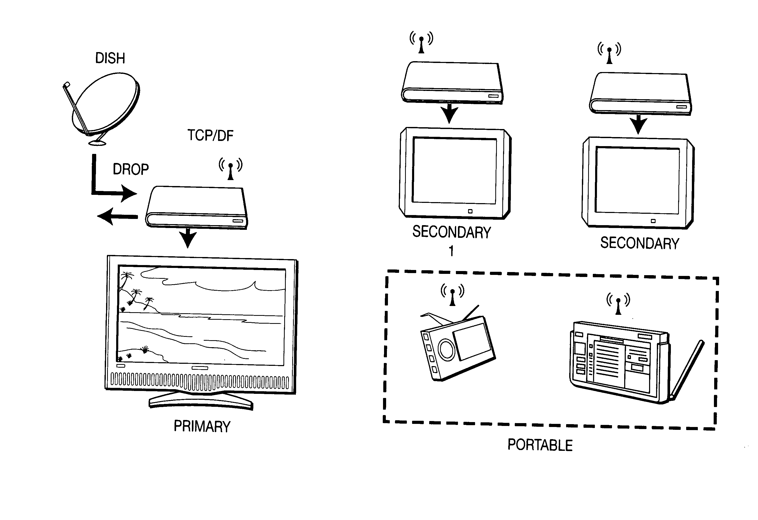
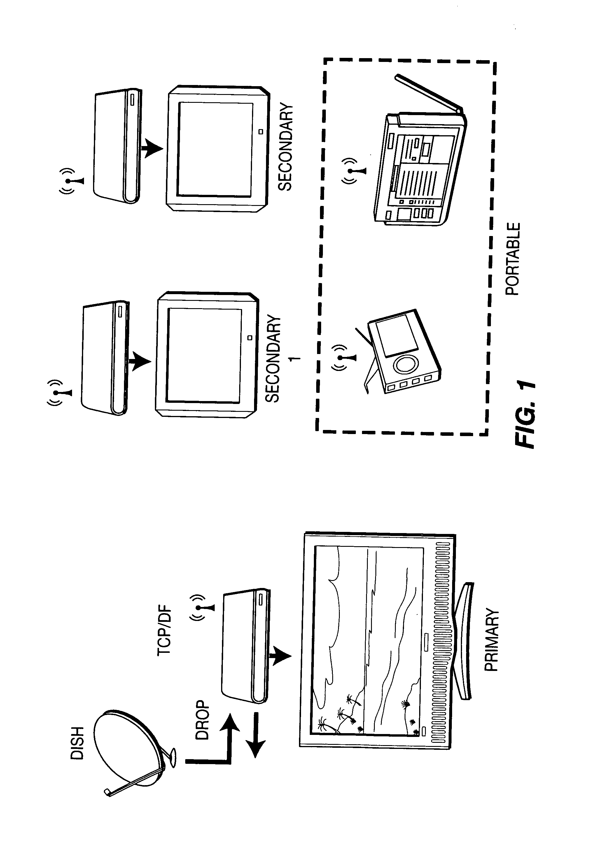
[0043]Emerging technologies such as orthogonal frequency division multiplexing (OFDM) and multiple in-multiple out (MIMO) make bandwidth demanding multimedia applications over wireless channels possible. In IEEE 802.11n, throughput over a 20 MHz or 40 MHz channel can reach 130 Mbps or 300 Mbps respectively. Transport of a high-definition video stream may need 15 Mbps to 20 Mbps of bandwidth. A typical in-home wireless video distribution system streams two or three HD / SD TV and video-on-demand (VoD) programs from a master set top box (STB) to slave STBs as shown in FIG. 1. For single home deployment, if the distance between homes is large enough, the number of interfering neighbors may be smaller than the total channels available. It would, therefore, be possible for an in-home wireless network to find an interference free channel.

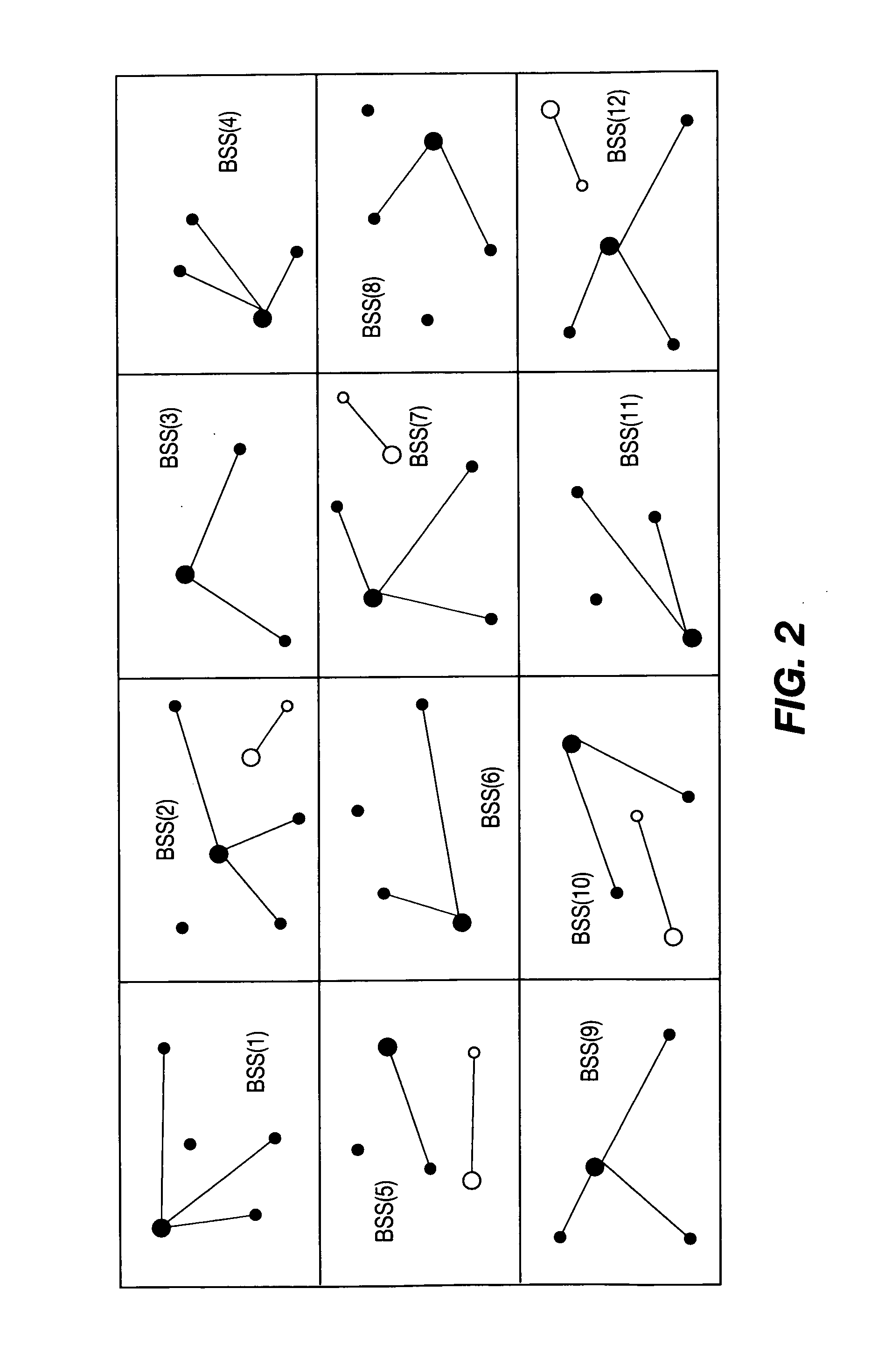
[0044]This may not be the case for multi-dwelling unit (MDU) deployment as shown in FIG. 2. One AP and its associated STAs form a basic service set (BSS). ...


PUM


Abstract

A method and apparatus are described including scanning a channel, generating a report for the scanned channel, transmitting the channel report to an associated access point and receiving a channel assignment responsive to said channel report. Also described are a method and apparatus including scanning a channel, generating a first channel report, receiving a second channel report from an associated client, transmitting the first channel report and the second channel report to a server, receiving a channel assignment message from the server responsive to the first and second channel reports and transmitting the channel assignment message to the associated client. Further described are a method and apparatus including receiving a channel report from an associated access point, building an interference graph responsive to the channel report, determining channel assignments based on the interference graph and transmitting a channel assignment message to the associated access point.

Description

FIELD OF THE INVENTION[0001]The present invention relates generally to wireless local area networks (WLANs) and, in particular, to channel assignment methods and apparatus in dense deployment environments.BACKGROUND OF THE INVENTION[0002]As used herein, “ / ” denotes alternative names for the same or similar components or structures. That is, a “ / ” can be taken as meaning “or” as used herein. Unicast transmissions are between a single sender / transmitter and a single receiver. Broadcast transmissions are between a single sender / transmitter and all receivers within receiving range of the transmitter. Multicast transmissions are between a single sender / transmitter and a subset of the receivers within receiving range of the transmitter where the subset of receivers with receiving range of the transmitter may be the entire set. That is, multicast may include broadcast and is therefore a broader term than broadcast as used herein. Data / content is transmitted in packets or frames. As used he...

Claims


Application Information

Patent Timeline
Patent Type & Authority Applications(United States)
IPC IPC(8): H04W72/04H04W84/12H04W72/54
CPCH04W72/082H04W74/0808H04W72/044H04W48/16H04W24/10H04W72/541H04W72/23
Inventor WU, MINGQUANLIU, HANGMANDREKAR, ISHANPERUMANAM, RAMKUMARMATHUR, SAURABH
Owner THOMSON LICENSING SA
Learn More