
Radio communication system

a communication system and radio technology, applied in the field of radio communication systems, can solve the problems of degraded throughput performance, and large variance in delay time between end terminals

Inactive Publication Date: 2005-08-23
NIPPON TELEGRAPH & TELEPHONE CORP
View PDF6 Cites 35 Cited by
  • Summary
  • Abstract
  • Description
  • Claims
  • Application Information

AI Technical Summary

Benefits of technology

[0010]It is also an object of the present invention to provide a radio communication system for packet communication in a multi-hop radio communication network having a small delay time, small delay time variance, high throughput performance, and achieving quality of service (Q0S).

Problems solved by technology

However, when said CSMA / CA system which uses a distributed control access system is used in a multi-hop radio communication network, a competition occurs in each link, and because re-transmission is inevitable in case of a competition, a delay time between end terminals has much variance.
Further, when a link is full, the transmission must wait until the link becomes available, and therefore, a delay time increases, thus, a throughput performance is degraded.
However, when said CSMA / CA system which uses a distributed control access system is used in a multi-hop radio communication network, a competition occurs in each link, and because re-transmission is inevitable in case of a competition, a delay time between end terminals has much variance.
Further, when a link is full, the transmission must wait until the link becomes available, and therefore, a delay time increases, thus, a thoughtput performance is degraded.
However, in case of a multi-hop radio network, a single master station cannot control all the radio stations.
Therefore, a prior polling system, and / or a prior polling / CSMA system cannot be used in a multi-hop radio network.

Method used


Image

  • Radio communication system
  • Radio communication system
  • Radio communication system

Examples


Embodiment Construction

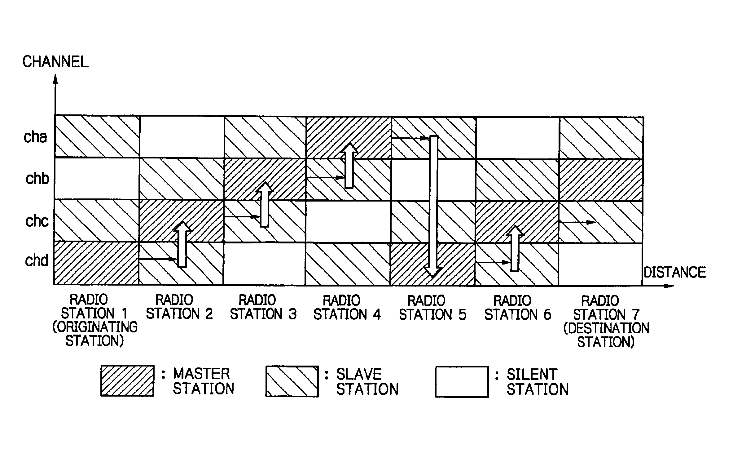
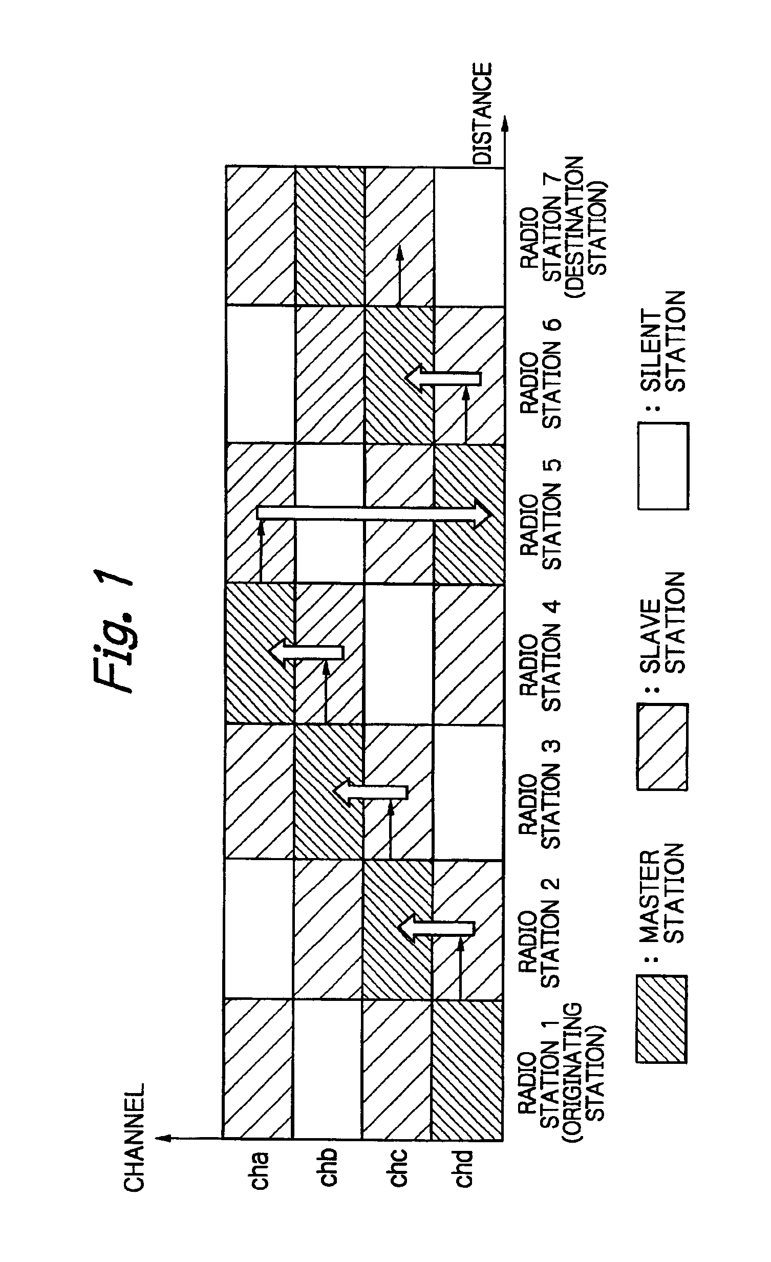
[0030]FIG. 1 shows channel configuration for a packet transmission system according to the present invention. A method for determining a path between radio stations in a network having a plurality of radio stations has been known, for example, as AODV method (Adhoc On-demand Distance Vector).

[0031]In FIG. 1, four channels, channel (a) through channel (d), are used to transmit a packet from a first radio station 1, which is an originating station, to a destination station 7 through radio stations 2, 3 , , , 6. Each radio station is in one of operation modes of a master station, a slave station, and a silent station in a centralized control access system. As shown in FIG. 1, when communication is carried out between the station 1 and the station 2, a channel (c) or a channel (d) between radio stations 1 and 2 with master / slave relationship is used under a centralized control access system. In the channel (c), the radio station 1 is a slave station and the radio station 2 is a master s...


PUM


Abstract

Each radio station can manage a plurality of channels, and functions both as a master station which controls transmission in each channel and a slave station which operates under control of a master station. In case of a master station, it transmits a signal under control of the own station, and in case of a slave station, it transmits a signal under control of the master station. Each radio station can communicate with any other radio station either directly or through another radio station. In each channel, communication is carried out in time division of centralized control access phase and distributed control access phase. A master station in case of centralized control access phase is determined in each channel and in each link.

Description

BACKGROUND OF THE INVENTION[0001]1. Field of the Invention[0002]The present invention relates to a radio communication system, in particular, relates to a multi-hop radio communication system having a plurality of radio links.[0003]2. Description of the Related Art[0004]In a radio packet communication system such as a radio LAN (local area network) system and / or a mobile communication system, a CSMA / CA (Carrier Sense Multiple Access with Collision Avoidance) has been known as a distributed control access system. In that system, it is tested for a predetermined duration whether a channel to which a signal is to be transmitted is available or busy, before a data packet is transmitted, thus, the possibility of collision of packets is decreased. That system is described in ANSI / IEEE Std802.11 Wireless LAN Medium Access Control (MAC) and Physical Layer (PHY) specification, and is taken as MAC protocol of IEEE802.11 standard.[0005]However, when said CSMA / CA system which uses a distributed...

Claims


Application Information

Patent Timeline
IPC IPC(8): H04L12/28H04L12/56
CPCH04W74/02H04W40/24H04W84/18
Inventor MIZUNO, KOHEIKUDOH, EISUKESUDA, HIROHITO
Owner NIPPON TELEGRAPH & TELEPHONE CORP
Learn More