Reciprocating compressor or pump and a portable tool powering system including a reciprocating compressor

a reciprocating compressor and compressor technology, applied in the direction of conductors, flexible pipes, couplings, etc., can solve the problems of pin premature failure when significantly reduced in scale, pneumatic tools requiring a steady source of compressed air for operation, and the mobility of conventional air compressors is often limited

Inactive Publication Date: 2007-12-20
SCHUETZLE LARRY ALVIN
View PDF65 Cites 14 Cited by
  • Summary
  • Abstract
  • Description
  • Claims
  • Application Information

AI Technical Summary

Benefits of technology

[0091] Preferably a depth of the circumferential recess is sufficient to prevent complete withdrawal of the resilient band from the circumferential recess under stretching by the compressed gas.

Problems solved by technology

The user of a pneumatic tool requiring a steady source of compressed air for operation is usually limited in mobility by a length of air hose connected to an air compressor that is stationary, or at least limited in mobility.
A conventional air compressor is often limited in mobility due to a large tank for storing compressed air, a non-electric motor driving the compressor that may emit harmful gases and requires a fuel source that adds weight and dimension, or an electric motor requiring connection to a fixed power source such as an AC outlet.
Such pins may prematurely fail when significantly reduced in scale for use in a compact portable device and may involve a significant number of assembly steps to complete connection between the master connecting rod and all of the pistons.
However, such battery-powered types of compressors typically do not provide enough airflow to be useful for powering pneumatic tools, which require relatively high amounts of air pressure provided on a relatively continuous basis for optimal operation.
These valves may break off or fail to seat properly after repeated exposure to the bending stresses experienced in their operation.
Metal reeds also retain heat which may be considered wasted energy and may corrode over time with exposure to moisture.
Conventional pumps used, for example, to withdraw production-inhibiting water from oil and gas wells, may fail relatively quickly when run continuously with exposure to brackish water or other fluids containing abrasive particulate material such as sulfur or sand.
More particularly, the reeds in such a pump may wear or corrode at an increased rate as a result of such exposure.

Method used


Image

  • Reciprocating compressor or pump and a portable tool powering system including a reciprocating compressor
  • Reciprocating compressor or pump and a portable tool powering system including a reciprocating compressor
  • Reciprocating compressor or pump and a portable tool powering system including a reciprocating compressor

Examples


first embodiment

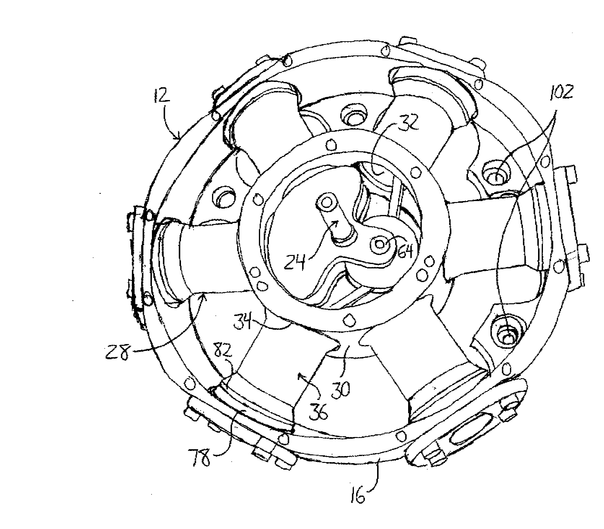
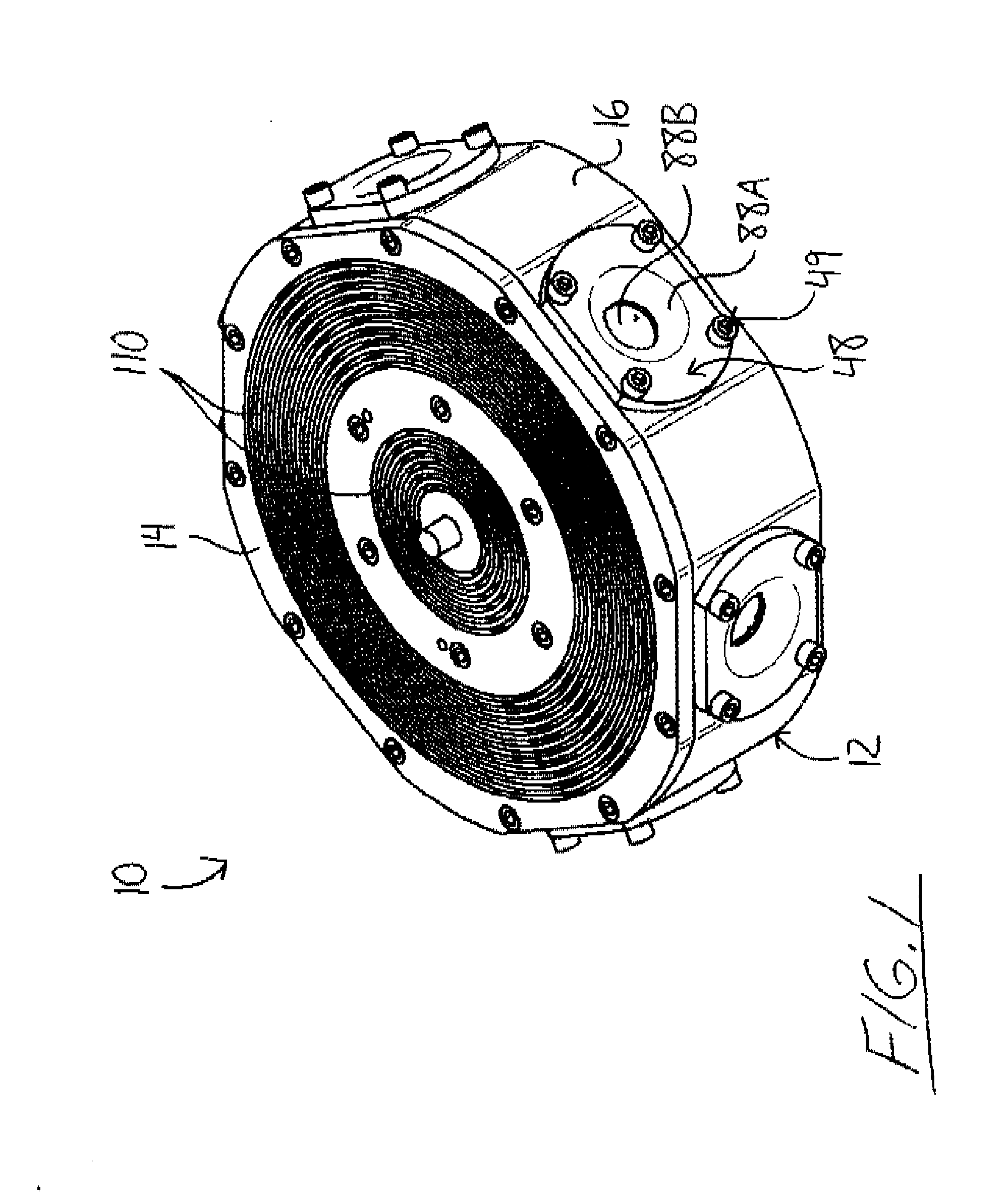
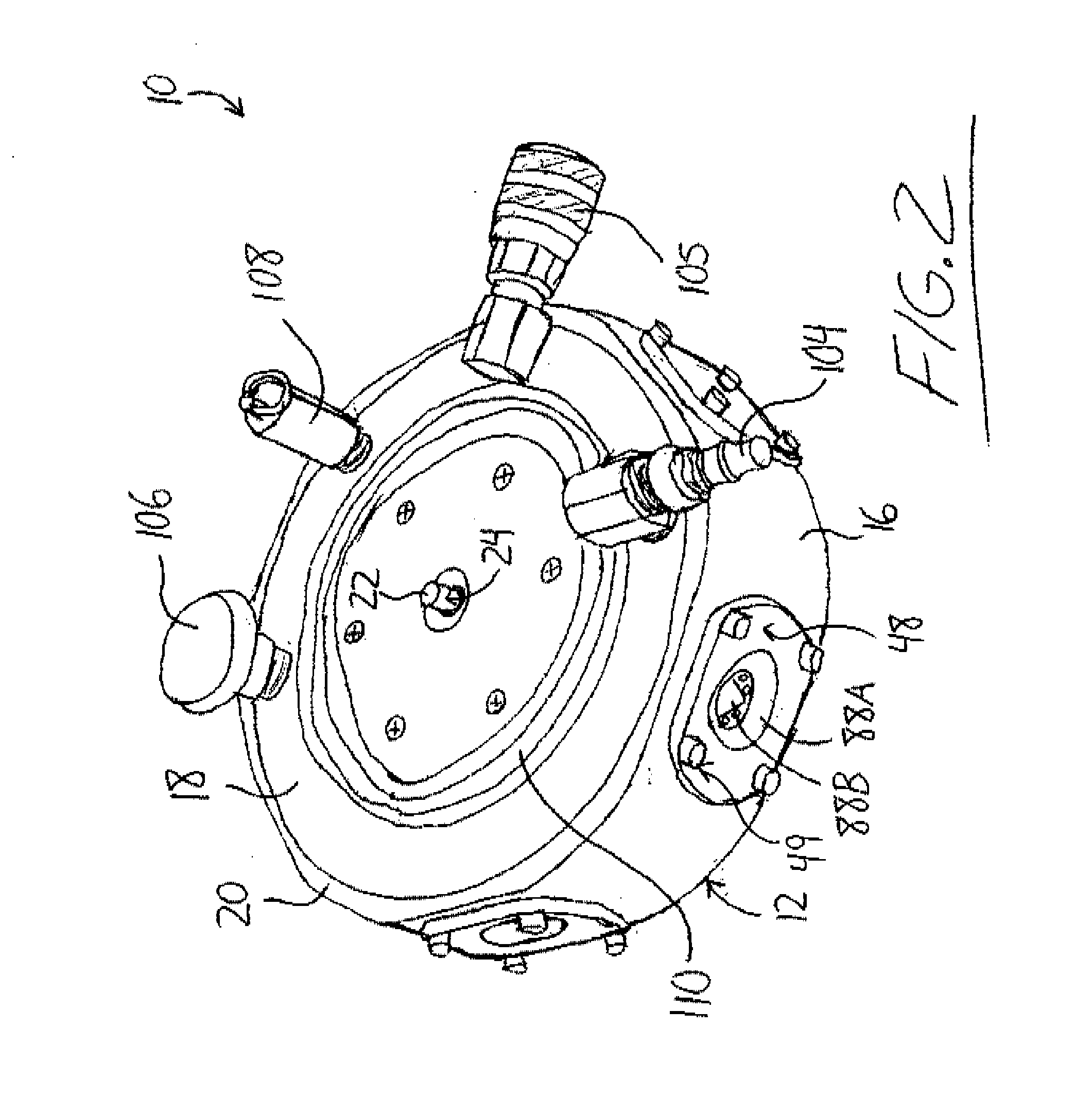
[0186] The housing 12 features an interior annular cylindrical wall 30 disposed concentrically within the exterior wall 16. Annular spacing between the two walls forms a receiving compartment in which the gas compressors 28 are disposed, extending radially between the two annular walls. In the first embodiment, the plurality of gas compressors includes six compressors arranged in diametrically opposed pairs and evenly spaced about the central axis of the housing 12. The space within the interior wall 30 defines a crankshaft compartment for housing components of the compressor's drive system. The interior wall 30 features round through-holes 32 each of which receives a drive end 34 of a cylinder liner 36 of a respective gas compressor 28, A valve end 38 of the cylinder liner 36 opposite the drive end 34 is received in a through-hole 40 provided in the exterior wall 16 axially aligned with the respective though-hole 32 in the interior wall 30.

[0187]FIG. 5 shows one of the gas compress...

second embodiment

[0219] As shown in FIGS. 10 and 11 the second embodiment compressor 200 does not feature a unitary housing, but instead includes two separate housings. A receiver housing 202 defines a manifold into which compressed gas is exhausted from the cylinder liners 36 and is formed by a bottom half 203 and a top half 204 which mate together with the cylinder liners 36 disposed between them. With its halves mated together, the receiver housing 202 is annular in shape so as to define a central opening 206. A crank housing 208 is positioned within the central opening 206 of the receiver housing 202 and similarly has an annular shape defining a central opening, within which the body of the master connecting rod 52 and the crank pin are disposed. The cylinder liners 36 are received in openings 210 extending radially through the annular crank housing 208 from the central opening thereof toward the surrounding receiver housing 202. The cylinder liners 36 are sealed to the crank housing 208 at thes...

third embodiment

[0244] A base 302 of the third embodiment compressor 300 supports three gas compressors 28 equally spaced about and extending radially relative to a central axis of the base 302. The base 302 is a block of solid material having two identical, flat, parallel opposing faces 304, 306 with a periphery defining a constant thickness of the body 302 perpendicular to the opposing faces 304, 306 that is significantly less than the span of the identical faces 304, 306. The periphery of the body 302 is shaped such that the body has the appearance of having been formed from an irregular hexagonal body with three long sides of identical length and three shorter sides of identical length, the short and long sides alternating along the periphery of the hexagonal body, which has had the long sides each equally recessed toward the center of the body along the opposed faces 304, 306. Looking at the plan view of FIG. 24A, each resulting recessed longer side 308 of the body 302 is made up of three line...


PUM


Abstract

A reciprocating compressor or pump features a manifold arranged not only to define a hollow interior for receiving fluid discharged from a plurality of cylinders but also to define a base or frame on which the cylinders are carried. Unique valves formed in part by flexible material reduces the likelihood of fatigue and increases efficiency by retaining less heat relative to conventional reed valves. A compressor or pump mounted at an end of a handle extending parallel to a motor housing likewise extending from the compressor or pump provides an easy to carry portable assembly. A fan mounted between a motor and a compressor pulls air through the compressor inlet to both cool the motor and feed the compressor. A portable tool system powers both pneumatic and electric tools. Connecting rod structures for radial compressors or pumps provide improved strength and easier assembly.

Description

[0001] This application claims the benefit under 35 U.S.C. 119(e) of U.S. provisional application Ser. No. 60 / 804,216, filed Jun. 8, 2006.FIELD OF THE INVENTION [0002] This invention relates to compressors and pumps, and more particularly to cylinder and piston based reciprocating compressors and pumps. BACKGROUND OF THE INVENTION [0003] The user of a pneumatic tool requiring a steady source of compressed air for operation is usually limited in mobility by a length of air hose connected to an air compressor that is stationary, or at least limited in mobility. A conventional air compressor is often limited in mobility due to a large tank for storing compressed air, a non-electric motor driving the compressor that may emit harmful gases and requires a fuel source that adds weight and dimension, or an electric motor requiring connection to a fixed power source such as an AC outlet. [0004] U.S. Pat. Nos. 6,692,239 and 6,589,024 of Nishikawa et al. and U.S. Pat. No. 5,030,065 of Baumann ...

Claims


Application Information

Patent Timeline
Patent Type & Authority Applications(United States)
IPC IPC(8): F04B1/04
CPCF04B1/0404H02J7/0063F04B1/0452F04B27/053F04B35/04F04B35/06F04B39/066F16L37/23F04B1/0439F04B1/053F04B39/121F04B39/123F04B39/127F04B53/16H01B7/0072F04B1/0421F04B39/0005F04B39/0022F04B39/0094F04B53/12F04B53/14F04B1/04F04B1/0533F04B39/12F16L11/118F16L11/127F04B35/00F04B39/10F04B39/122F04B41/06
Inventor SCHUETZLE, LARRY ALVINPENNER, LLOYD DEAN
Owner SCHUETZLE LARRY ALVIN
Why Eureka
Try Eureka