
Anisotropic conductive connector and circuit-device electrical inspection device

a technology of anisotropic conductive connectors and electrical inspection devices, which is applied in the direction of coupling device connections, semiconductor/solid-state device details, instruments, etc., can solve the problem of difficulty in sufficiently controlling the noise of high-frequency signals

Inactive Publication Date: 2007-12-20
JSR CORPORATIOON
View PDF40 Cites 7 Cited by
  • Summary
  • Abstract
  • Description
  • Claims
  • Application Information

AI Technical Summary

Benefits of technology

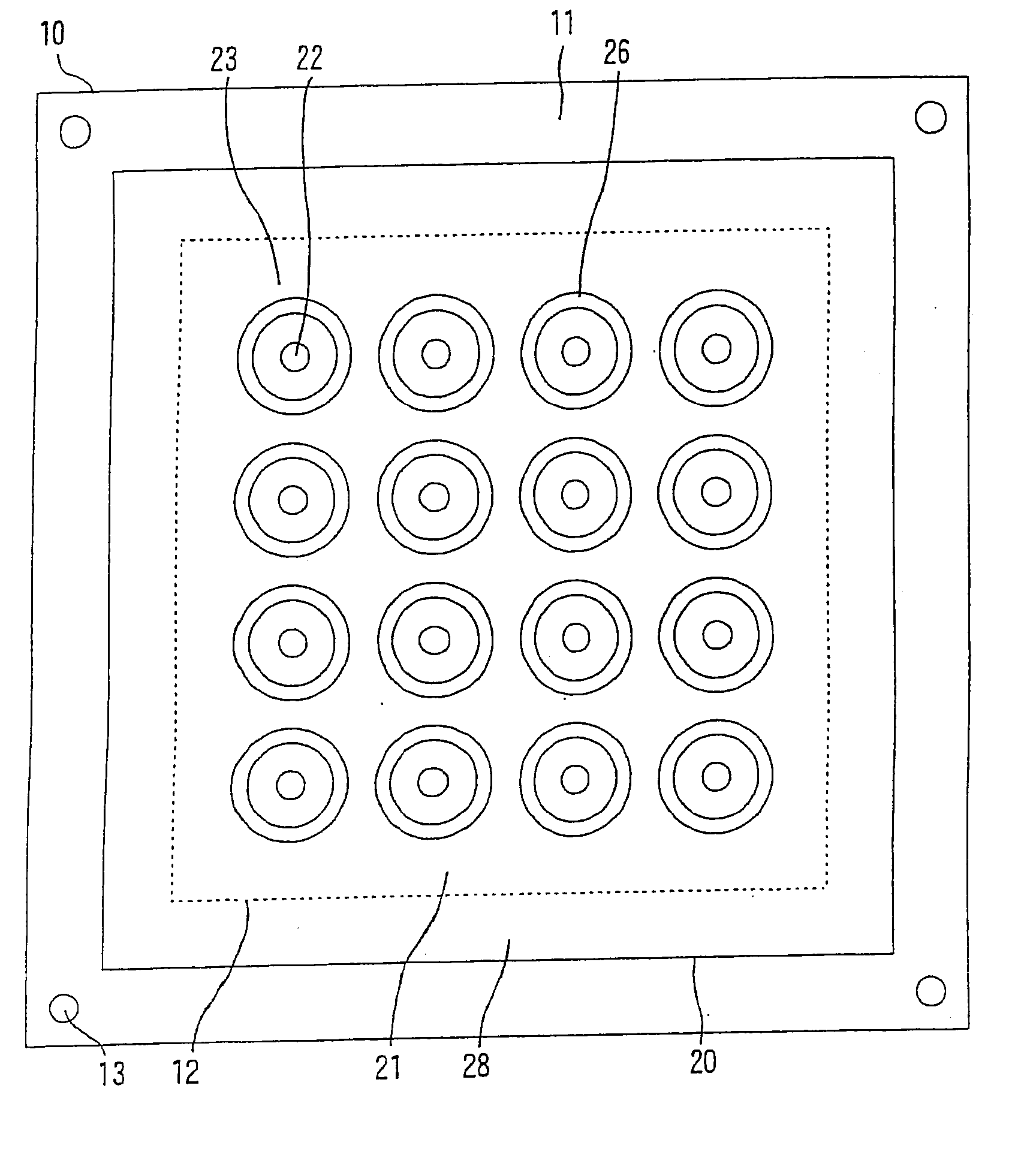
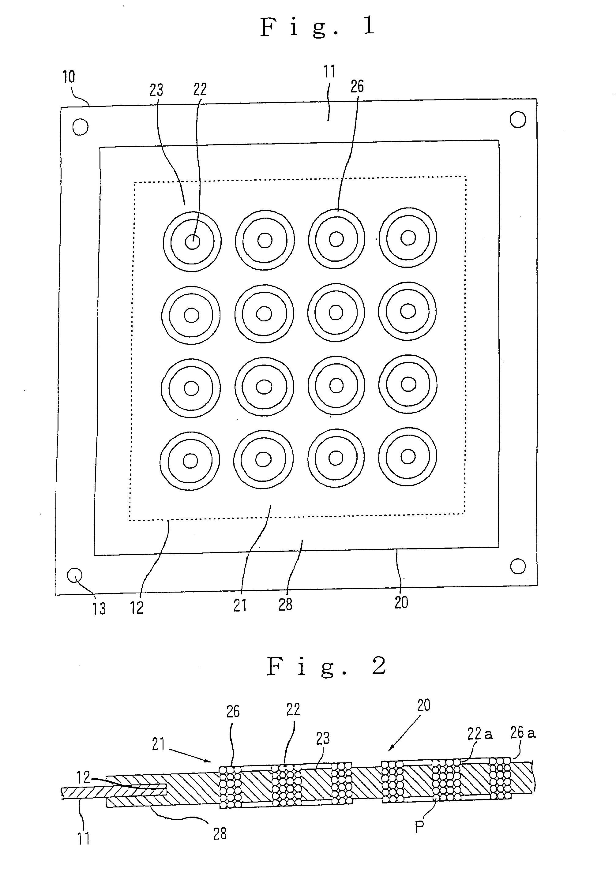
[0051] According to the anisotropically conductive connectors of the present invention, in addition to the conductive parts for connection electrically connected to electrodes that are an object of connection, the conductive parts for high-frequency shielding extending in the same direction as the conductive parts for connection are formed in the elastic anisotropically conductive film, so that external noises to high-frequency signals and noises from adjoining conductive parts for connection can be controlled in each of the conductive parts for connection by connecting the conductive parts for high-frequency shielding to a ground. Accordingly, in the case where the anisotropically conductive connector according to the present invention is used in the electrical inspection of a circuit device, an expected electrical inspection can be performed as to the circuit device, which is an object of inspection, without being influenced by the noises even when the clock frequency of the circuit device is, for example, at least 1 GHz.
[0052] According to the electrical inspection apparatus for circuit devices of the present invention, any one of the above-described anisotropically conductive connectors is provided, so that both external noises to high-frequency signals and noises from adjoining conductive parts for connection can be controlled in each of the conductive parts for connection by connecting the conductive parts for high-frequency shielding in the anisotropically conductive connector to a ground. Accordingly, expected electrical inspection as to a circuit device, which is an object of inspection, can be performed without being influenced by the noises even when the clock frequency of the circuit device is, for example, at least 1 GHz.

Problems solved by technology

However, according to such a means, it is difficult to sufficiently control the noises to the high-frequency signals when electrical inspection is conducted as to a circuit device having a clock frequency of, for example, at least 1 GHz.

Method used


Image

  • Anisotropic conductive connector and circuit-device electrical inspection device
  • Anisotropic conductive connector and circuit-device electrical inspection device
  • Anisotropic conductive connector and circuit-device electrical inspection device

Examples


example 1

[0313] An anisotropically conductive connector (10) according to the present invention was produced under the following conditions in accordance with the construction illustrated in FIG. 14 and FIG. 15.

[0314] [Frame Plate (11)]

[0315] A frame plate of the following specification was produced.

[0316] Material: Stainless steel (JIS Standard Code: SUS304), dimensions: 10 mm×10 mm×0.1 mm, diameter of opening (12): 500 μm, the number of openings (12): 16 (4×4), arrangement pitch of openings (12): 1 mm. [Mold for Molding Elastic Anisotropically Conductive Film]

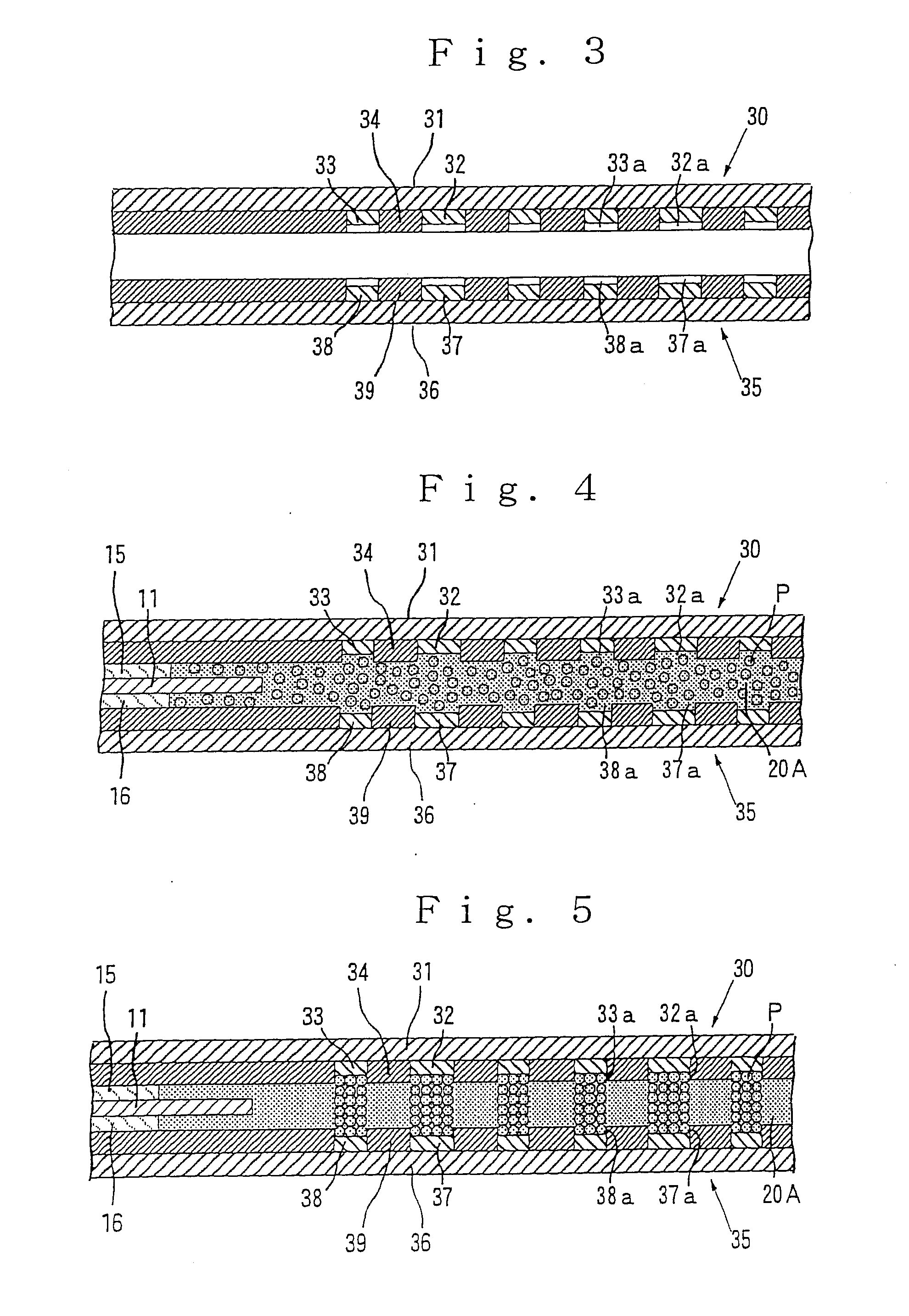
[0317] A mold for molding an elastic anisotropically conductive film composed of a top force (30) and a bottom force (35) of the following specification was produced in accordance with the construction illustrated in FIG. 3.

[0318] Ferromagnetic base plates (31, 36):

[0319] Material: steel material (JIS Standard Code: SS400),

[0320] Thickness: 6 mm.

[0321] Ferromagnetic substance layers (32, 37):

[0322] Material: nickel,

[0323] Diam...


PUM


Abstract

An anisotropically conductive connector having a frame plate, in which a plurality of openings have been formed in accordance with a pattern corresponding to electrodes to be connected, and an elastic anisotropically conductive film composed of a plurality of functional parts arranged in the respective openings of the frame plate. The conductive film is composed of a conductive part for connection extending in a thickness-wise direction of the film and an insulating part formed integrally with the conductive part. Conductive parts for high-frequency shielding are arranged to surround each of the conductive parts for connection, electrically connected to the frame plate and extending in the thickness-wise direction, and are formed in the part to be supported in the elastic anisotropically conductive film. The frame plate is connected to a ground.

Description

CROSS-REFERENCE TO RELATED APPLICATIONS [0001] This application is a continuation of and claims the benefit of priority from U.S. Ser. No. 10 / 552,995, filed Oct. 13, 2005, and now allowed, which is a National Stage application under 35 U.S.C. § 371 of International Application PCT / JP04 / 04891, filed Apr. 5, 2004, and is based upon and claims the benefit of priority from Japanese Patent Application No. 2003-111225, filed Apr. 16, 2003, the entire contents of all of which are incorporated herein by reference.BACKGROUND OF THE INVENTION [0002] 1. Field of the Invention [0003] The present invention relates to an anisotropically conductive connector and an electrical inspection apparatus for circuit devices, which is equipped with this anisotropically conductive connector, and more particularly to an anisotropically conductive connector and an electrical inspection apparatus for circuit devices, which are suitable for use in electrical inspection of a circuit device having a clock frequen...

Claims


Application Information

Patent Timeline
Patent Type & Authority Applications(United States)
IPC IPC(8): H01R4/58G01R1/073H01L23/498H01R13/24
CPCG01R1/0735H01L23/49827H01L23/49838H01R13/2414H01L2924/0002H01L2924/00H01R13/646H01R43/00H01R11/01
Inventor SATO, KATSUMIINOUE, KAZUO
Owner JSR CORPORATIOON
Learn More