Brushless motor having chucking mechanism, and disk driving device having the brushless motor

a brushless motor and disk drive technology, which is applied in the direction of dynamo-electric components, data recording, instruments, etc., can solve the problems of minor unbalance in the rotation of the lens, the inability to record data on the optical disk or reproduce, and the disc may vibrate severely, so as to reduce the problem of misalignment of the optical disk, the effect of improving the strength of the optical disk and reducing the number of optical disks

Active Publication Date: 2007-12-20
NIPPON DENSAN CORP
View PDF23 Cites 34 Cited by
  • Summary
  • Abstract
  • Description
  • Claims
  • Application Information

AI Technical Summary

Benefits of technology

[0011]According to a conventional motor having a plurality of aligning claws circumferentially arranged for making contact with a portion of the central opening portion of the optical disk so as to retain the optical disk, when the rotation of the motor reaches approximately 6,000 rpm, the centrifugal force imposed on the optical disk becomes greater than the retaining strength

Problems solved by technology

In recent years, due to a very high speed rotation of an optical disk such as CDs and DVDs, when a mechanism for rotating the disk has a balance problem, the disk may vibrate severely.
The vibration may cause a problem when recording data on the disk or reproducing data from the disk.
Currently due to lack of standardization for different types of high density optical disks (e.g., HD-DVD, Blu-ray), each type of optical disk requires a specific optical pickup mechanism.
That is to say that the lens arranged further away from the brushless motor will not be able to record data on the optical

Method used


Image

  • Brushless motor having chucking mechanism, and disk driving device having the brushless motor
  • Brushless motor having chucking mechanism, and disk driving device having the brushless motor
  • Brushless motor having chucking mechanism, and disk driving device having the brushless motor

Examples


Embodiment Construction

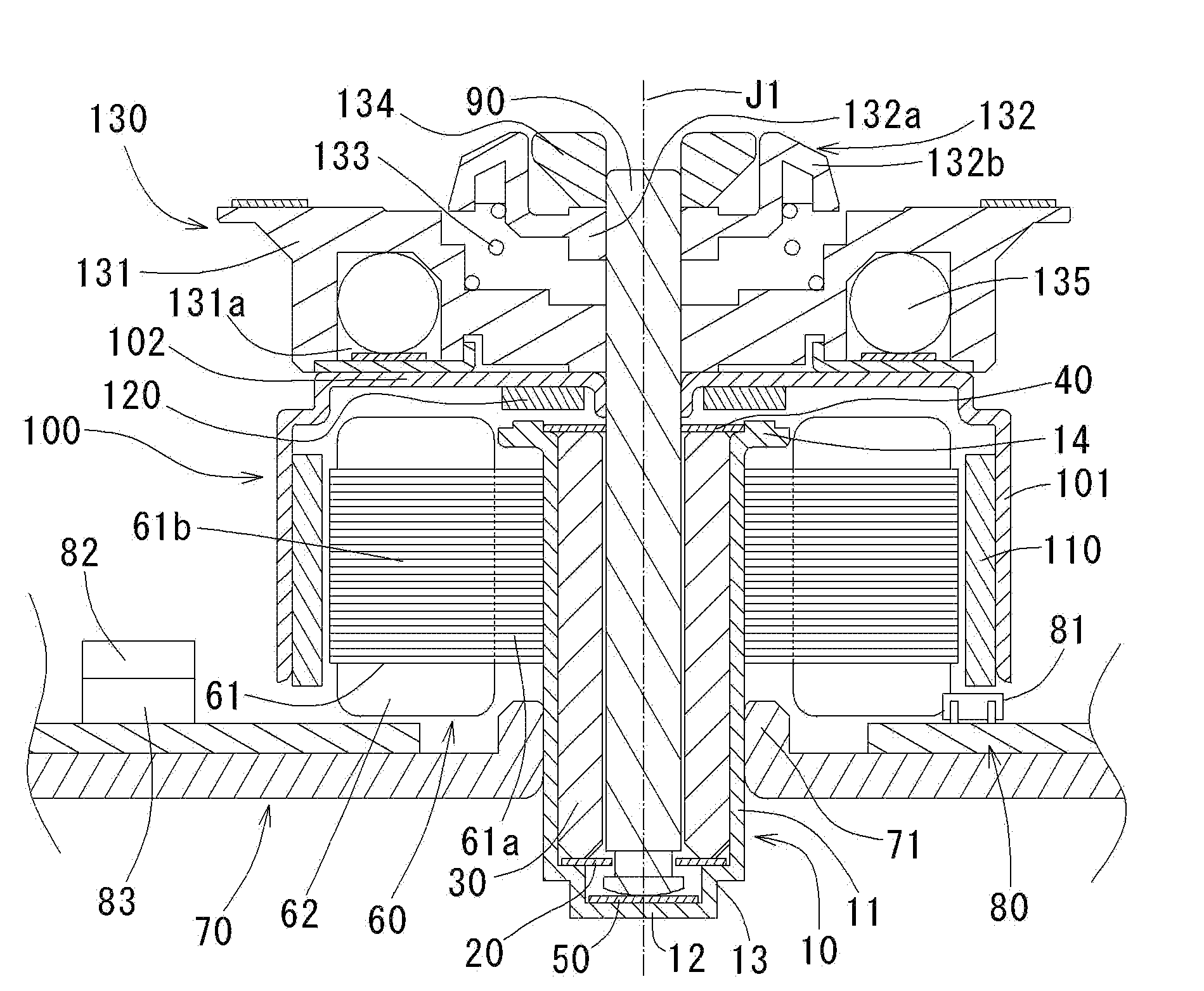
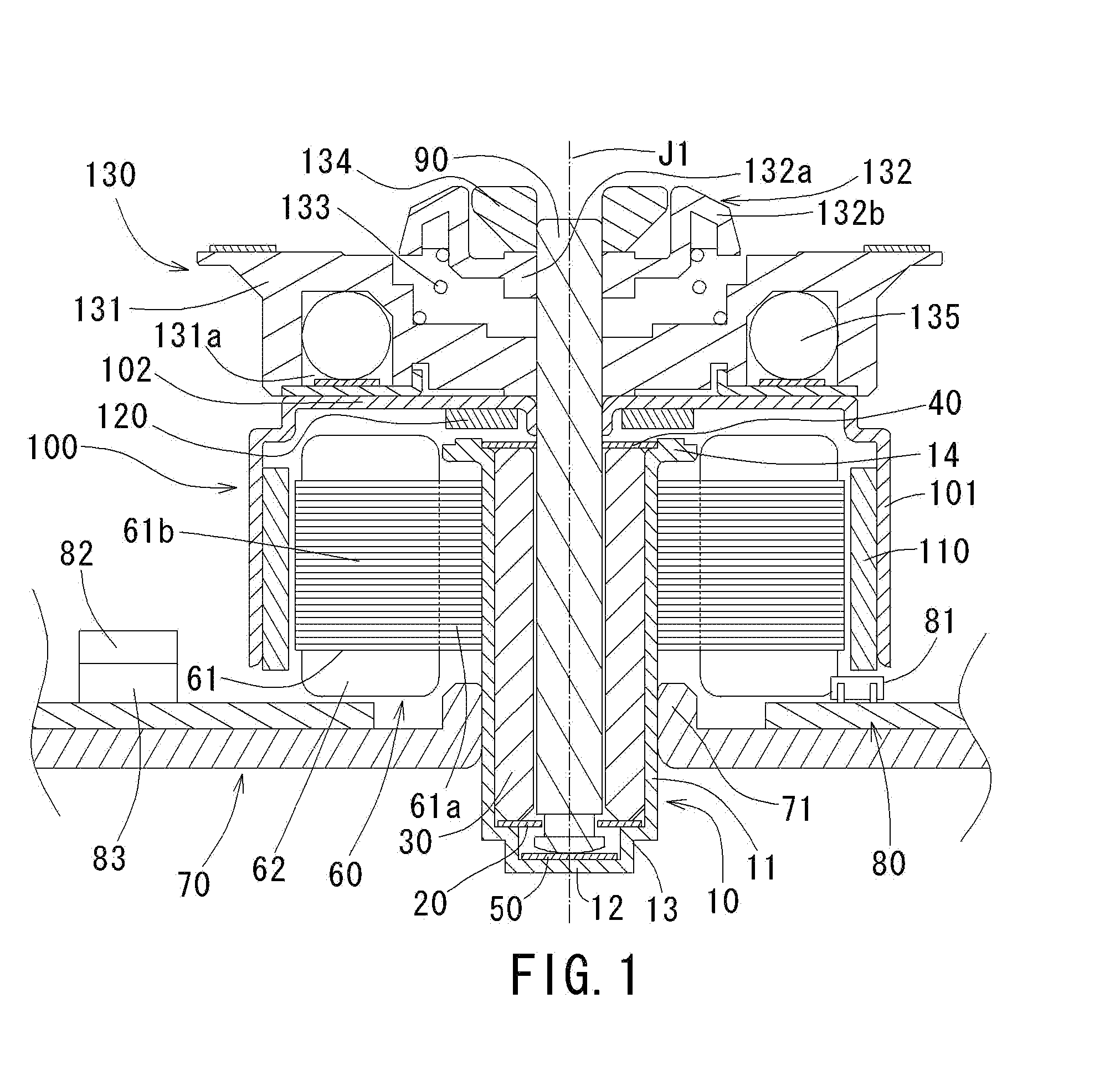
Structure of Brushless Motor

[0022]Note that in the description of a preferred embodiment of the present invention herein, words such as upper, lower, left, right, upward, downward, top and bottom for describing positional relationships between respective members and directions merely indicate positional relationships and directions in the drawings. Such words do not indicate positional relationships and directions of the members mounted in an actual device. Also note that reference numerals, figure numbers and supplementary descriptions are shown below for assisting the reader in finding corresponding components in the description of the preferred embodiment below to facilitate the understanding of the present invention. It is understood that these expressions in no way restrict the scope of the present invention. Note that reference numerals, figure numbers and supplementary explanations are shown in parentheses below for assisting the reader in finding corresponding components in ...


PUM


Abstract

A space for accommodating therein a portion of an optical pickup mechanism is arranged below a disk loading portion of a turn table member of a chucking mechanism of the present invention. The space is arranged axially below a disk mounting surface. Since such space is provided, a recording/reproducing portion will be allowed to move closer to a brushless motor, and therefore a second lens arranged further away from the brushless motor will be allowed to move radially inward of a recording/reproducing area of an optical disk.

Description

BACKGROUND OF THE INVENTION[0001]1. Field of the Invention[0002]The present invention relates to a brushless motor having therein a chucking mechanism allowing an optical disk to be detachably placed thereon, and to a disk driving device having therein the brushless motor.[0003]2. Description of the Related Art[0004]In recent years, due to a very high speed rotation of an optical disk such as CDs and DVDs, when a mechanism for rotating the disk has a balance problem, the disk may vibrate severely. The vibration may cause a problem when recording data on the disk or reproducing data from the disk. Therefore, a brushless motor having a balance correction feature has been developed.[0005]FIG. 7 indicates a conventional brushless motor 1 having the balance correction feature. According to FIG. 7, the brushless motor 1 includes a shaft 2a which rotates along the central axis J1, a rotor portion 2 having therein a rotor holder 2b of a substantially cylindrical shape affixed to the shaft 2...

Claims


Application Information

Patent Timeline
IPC IPC(8): G11B19/20G11B17/03
CPCG11B19/2009G11B17/0282H02K7/09
Inventor ITO, HARUHIKOSONODA, TOSHIHIDEYAMANE, TAKUYA
Owner NIPPON DENSAN CORP
Why Eureka
Try Eureka