Connector

a technology of connecting rods and connectors, applied in the direction of securing/insulating coupling contact members, coupling device connections, electrical devices, etc., can solve the problems of affecting the the width of the elastic retaining piece portion, and the adverse effect of achieving a compact design of the connector 201, etc., to achieve compact design of the connector, increase the strength of the retaining lance, and the effect of sufficient terminal retaining for

Active Publication Date: 2007-01-30
YAZAKI CORP
View PDF11 Cites 1 Cited by
  • Summary
  • Abstract
  • Description
  • Claims
  • Application Information

AI Technical Summary

Benefits of technology

[0015]This invention has been made in order to solve the above problems, and an object of the invention is to provide a connector in which a sufficient terminal-retaining force is obtained without increasing a width of a retaining lance, and also the strength of the retaining lance is increased so as to achieve a compact design of the connector.
[0019]In the present invention, the elastic retaining piece portion includes the pair of ribs which are formed in an upstanding manner, and are spaced from each other in the direction perpendicular to the direction of withdrawing of the terminal, and the retaining portion which extends between the pair of ribs and against which the retaining engagement portion of the terminal abuts in the withdrawing direction, and the end edges of the pair of ribs, disposed close to the retaining engagement portion, project forwardly beyond the retaining portion. Namely, that portion of the elastic retaining piece portion for receiving the retaining engagement portion of the terminal is formed into a generally U-shape by the retaining portion and the pair of ribs formed integrally with the retaining portion. With this construction, a shearing strength of the retaining portion can be enhanced, and therefore wear of the elastic retaining piece portion, developing upon abutment against the retaining engagement portion of the terminal, is suppressed, thereby securing the sufficient force of retaining of the terminal by the elastic retaining piece portion.
[0020]The pair of ribs are formed in an upstanding manner on the elastic retaining piece portion, and are spaced from each other in the direction perpendicular to the direction of withdrawing of the terminal. Namely, the pair of ribs do not project from the elastic retaining piece portion in the direction of the width thereof, and therefore the width of the elastic retaining piece portion can be reduced, thereby achieving a compact design of the connector.
[0021]With the elastic retaining piece portion of this simplified structure, the sufficient terminal-retaining force can be obtained, and besides the compact design of the connector can be achieved.
[0022]Furthermore, since the pair of ribs extend in the direction of withdrawing of the terminal, even the narrow elastic retaining piece portion can have a sufficient buckling strength, and therefore the terminal-retaining force of the elastic retaining piece portion can be further enhanced.
[0023]Furthermore, the jig for elastically deforming the elastic retaining piece portion so as to cancel the retaining engagement of the elastic retaining piece portion with the terminal is brought into engagement with the elastic retaining piece portion at the region between the pair of ribs, and the end edges of the pair of ribs serve as the guide portion for guiding the jig into the gap between the pair of ribs. With this construction, the portion of the elastic retaining piece portion with which the jig can be engaged is formed into a generally U-shape by the pair of ribs and the retaining portion, and the jig is guided by the pair of ribs (forming this engaging portion), and therefore the jig can be positively brought into engagement with the elastic retaining piece portion.

Problems solved by technology

However, as a result of formation of the projecting portions 208b, the width of the elastic retaining piece portion 204 increases, and therefore there has been a fear that the achievement of a compact design of the connector 201 is adversely affected.

Method used


Image

  • Connector
  • Connector
  • Connector

Examples


Embodiment Construction

[0042]A preferred embodiment of a connector of the present invention will now be described with reference to the drawings.

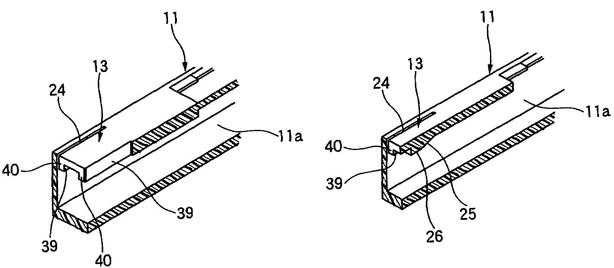
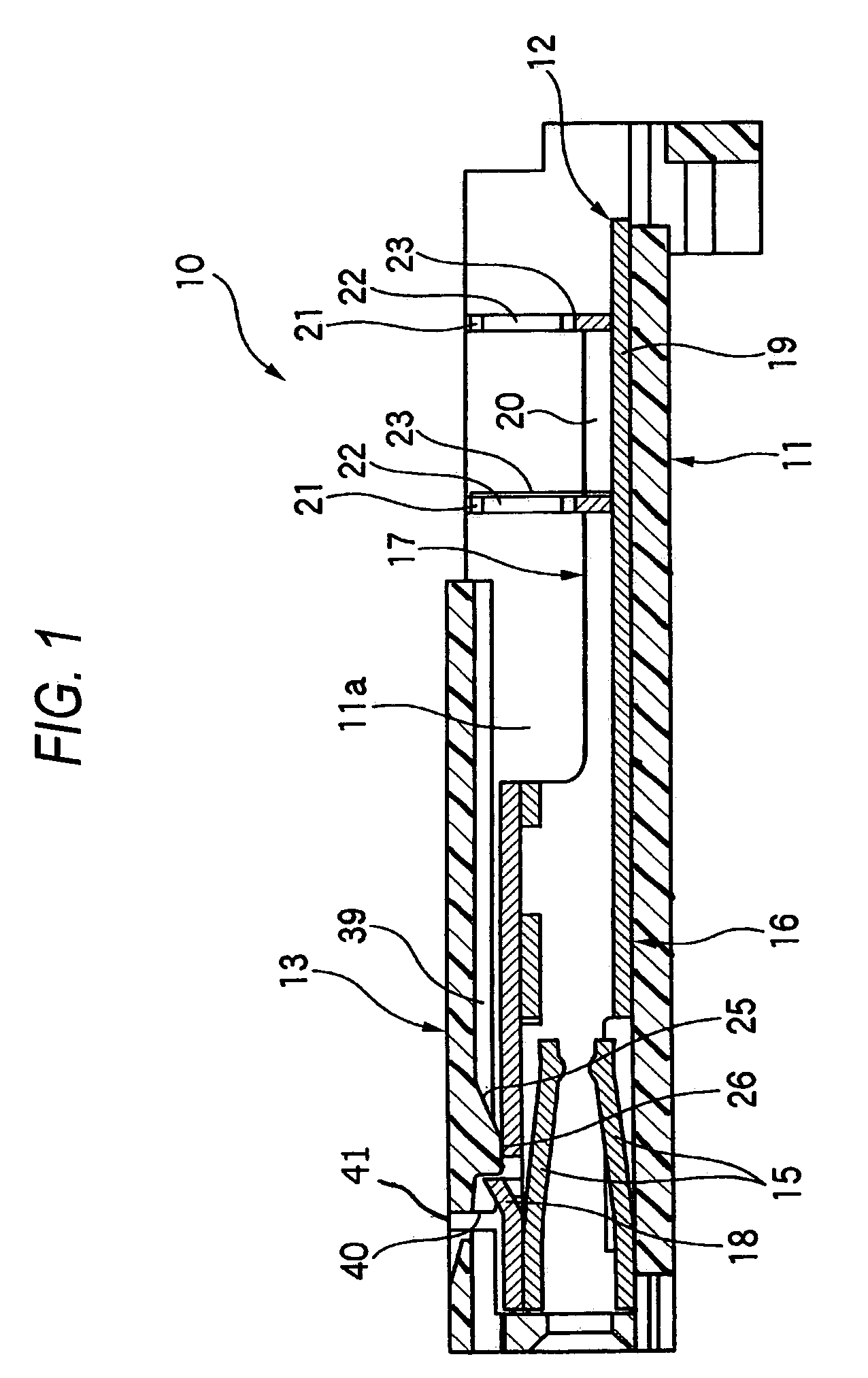
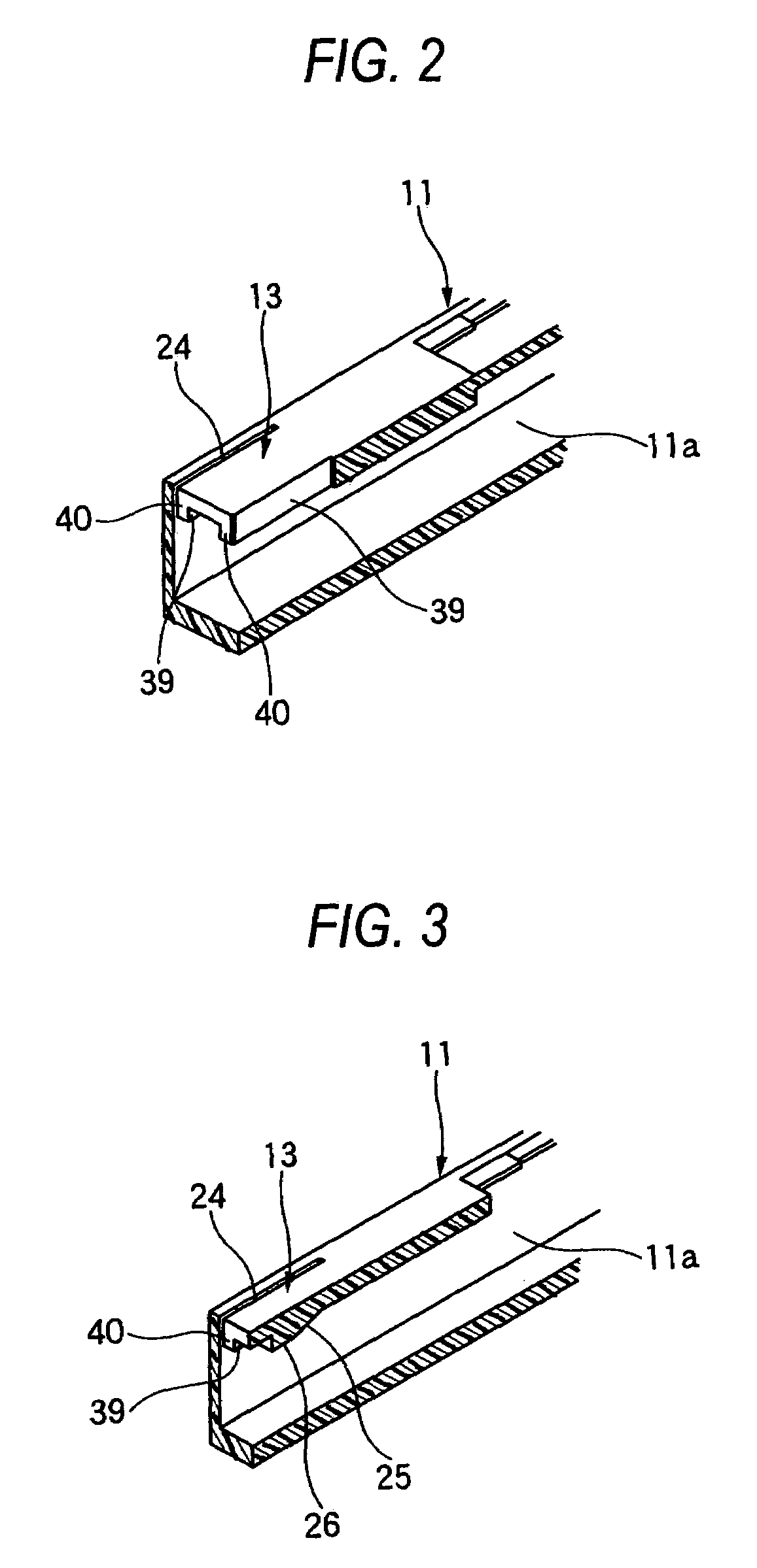
[0043]FIG. 1 is a cross-sectional view explanatory of one preferred embodiment of the connector of the invention, FIG. 2 is a partly-broken, perspective view of a connector housing of the connector of FIG. 1, showing an elastic retaining piece portion of the connector, and FIG. 3 is a perspective view, showing a condition in which the elastic retaining piece portion of FIG. 2 is broken along a direction of withdrawing of a terminal.

[0044]As shown in FIG. 1, the connector 10 of this embodiment includes the synthetic resin-made connector housing 11 having a terminal receiving chamber 11a, and the terminal 12 (which is formed by pressing an electrically-conductive metal sheet) is inserted into the terminal receiving chamber 11a through a rear opening thereof. The retaining lance (elastic retaining piece portion) 13 for retaining the terminal 12 received in the termi...


PUM


Abstract

A connector includes a connector housing that includes a terminal receiving chamber for receiving a terminal, and an elastic retaining member that is arranged to retain an engagement portion of the terminal. The elastic retaining member includes a pair of ribs that are spaced from each other in a first direction perpendicular to a second direction in which the terminal is inserted, and a retaining portion that extends between the pair of ribs, and that is arranged to abut against the engagement portion of the terminal.

Description

BACKGROUND OF THE INVENTION[0001]This invention relates to a connector having an elastic retaining piece portion for retaining a terminal received in a terminal receiving chamber of a connector housing.[0002]FIG. 4 and FIGS. 5 and 6 show known related connectors of the type described, respectively (see, for example, Patent Literature 1 and Patent Literature 2).[0003]In the connector 101 shown in FIG. 4, a terminal receiving chamber 103 is formed in a synthetic resin-made connector housing 102, and extends from a central portion thereof to a rear end thereof. An elastic retaining piece portion 105 is formed in a cantilever manner within the terminal receiving chamber 103, and extends obliquely forwardly from an upper wall portion 102a of the connector housing 102.[0004]When a terminal 108, connected to a wire 107, is inserted through a terminal insertion port 104 (formed in the rear end of the terminal receiving chamber 103) into the terminal receiving chamber 103, and is received th...

Claims


Application Information

Patent Timeline
Patent Type & Authority Patents(United States)
IPC IPC(8): H01R12/00
CPCH01R13/4223
Inventor SAKAMOTO, NOBUYUKI
Owner YAZAKI CORP
Why Eureka
Try Eureka